0
\$\begingroup\$

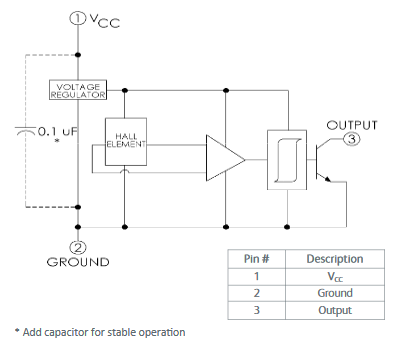
I am using the Hall-effect sensor OPTEK 3075S to ensure every step commanded to a stepper motor is executed. In the datasheet, they recommend connecting a 100nF capacitor across he input pins for "stable operation". I have been successfully using this sensor without cap with short supply wires for months, and now that I am planning on using this sensor after a few tens of meters I wonder if this is required.

enter image description here

I know it is easy enough to add the cap anyway (although I would need to build another PCB), but I do not like to add components without understanding their added value:

  1. how would the current source of the Hall element (which apparently is a voltage regulator across a constant resistance) be less stable without cap, given that there is nearly no load, and that the power supply rejection is not so important (since this is a digital sensor)?
  2. Certainly the opamp is the one which may become unstable? Is it possible that stability would only result in unstable transients but the output would not be affected after the step has been made?
  3. Is there a way to quantify/estimate the gain in stability margins by adding the cap in (with respect to what? Supply variations? Hall element output?)?

Note: the sensor state transitions are located dead-on between two steps (45° per step) for stable output for every motor positions, and the motor step rate is 5 steps per second.

\$\endgroup\$

3 Answers 3

4
\$\begingroup\$

There are several reasons to use the 100 nF capacitor: -

  1. The data sheet recommends it
  2. The internal chip current changes by 2 mA when it switches
  3. The external load (attached to the open collector output) might switch an extra 20 mA
  4. The supply voltage may not be a perfect voltage source i.e. it might have ESR and ESL components that would cause a ripple voltage on the supply when the device switches
  5. The cable supplying power to the chip might be long and have more ESR and ESL
  6. Switching times are around 100 ns i.e. it switches at a fairly high speed.

I don't see any good competant reason NOT to use it.

how would the current source of the Hall element (which apparently is a voltage regulator across a constant resistance) be less stable without cap, given that there is nearly no load, and that the power supply rejection is not so important (since this is a digital sensor)?

The first part is impossible to say without detailed knowledge of the device. There is an internal load and that load changes by 2 mA each time the device switches and, it switches in about 100 ns. There is a graph in the DS that shows this. Power supply rejection being unimportant is not a healthy place to start making a counter argument.

\$\endgroup\$
2
  • \$\begingroup\$ Thanks Andy. +1 for the 2mA surge upon switches for 100ns, which I had overlooked. I can't see why the 20mA load would come from the supply though as that's an open collector which will be connected to the acquisition reference. I'm going to do the test with long cables and look at the ringing, but after carefully analyzing how a 2mA surge would propagate through the functional block diagram, it seems the large output hysteresis makes caps unnecessary as the drops eventually settle before the acquisition. I'm interested on your opinion about that propagation :) \$\endgroup\$ Commented Feb 6, 2018 at 14:45
  • \$\begingroup\$ If the 20 mA O/C is on a different supply then this makes life easier for sure. I can't really comment on the propagation of 2 mA pulses because every application will be different and if you think yours works then who am I to tell you (other than point out what it says in the data sheet!). \$\endgroup\$
    – Andy aka
    Commented Feb 6, 2018 at 14:59
3
\$\begingroup\$

I think the capacitor is mainly needed for the voltage regulator. You probably know that most voltage regulators require decoupling capacitors and their input and output.

Is there a way to quantify/estimate the gain in stability margins by adding the cap in?

If you had the complete design (including transistor models) of the chip you could in theory simulate it. In the real works only the people who designed this sensor can do this.

A workaround could be to just try it with the long cables and use an oscilloscope to see how much ringing there is at the slopes of the signals and on the supply voltage of the sensor.

You could hand-solder a capacitor where it needs to be, repeat the measurements and look for any differences.

I guess that the manufacturer simply suggests to use a decoupling capacitor as that would eliminate a lot of issues with their customers beforehand.

\$\endgroup\$
1
\$\begingroup\$

I've diagnosed oscillations in Brown_out_Detectors, where the designers were ignoring the onchip gain-of-10,000,000 (yes 10 Million), interacting with the onchip bandgap voltage reference, and the lead inductance.

Put a cap right by the sensor.

So-----theoretically? Yes, the cap is required.

\$\endgroup\$
1
  • \$\begingroup\$ Thanks for the answer but that does not seem to be tailored for this specific question. \$\endgroup\$ Commented Feb 6, 2018 at 14:41

Your Answer

By clicking “Post Your Answer”, you agree to our terms of service and acknowledge you have read our privacy policy.

Not the answer you're looking for? Browse other questions tagged or ask your own question.