0
\$\begingroup\$

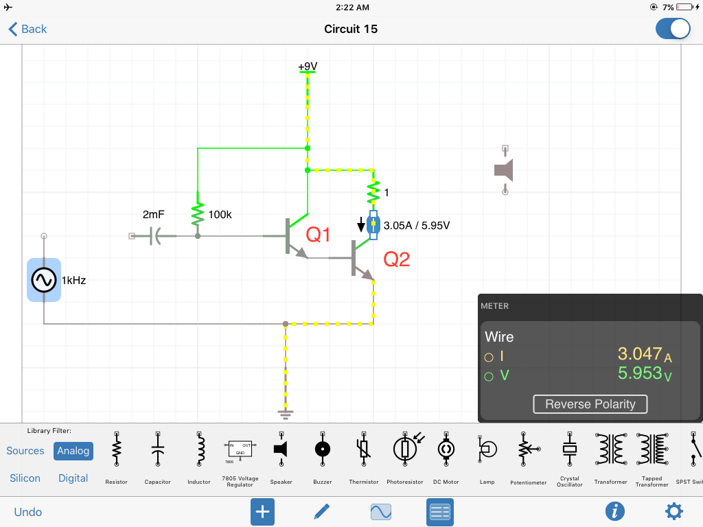
This is an audio amp that we built for a project.

I can easily find the first collector current from the first transistor by multiplying it with its Beta(200) and since the first transistor is beta dependent.

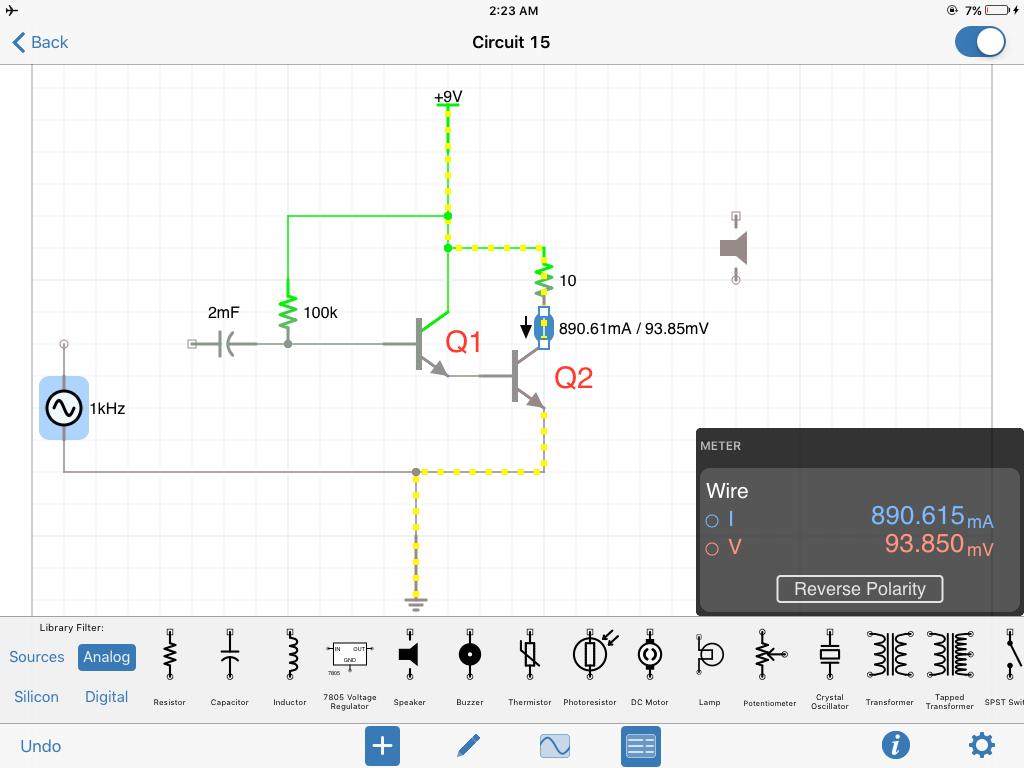
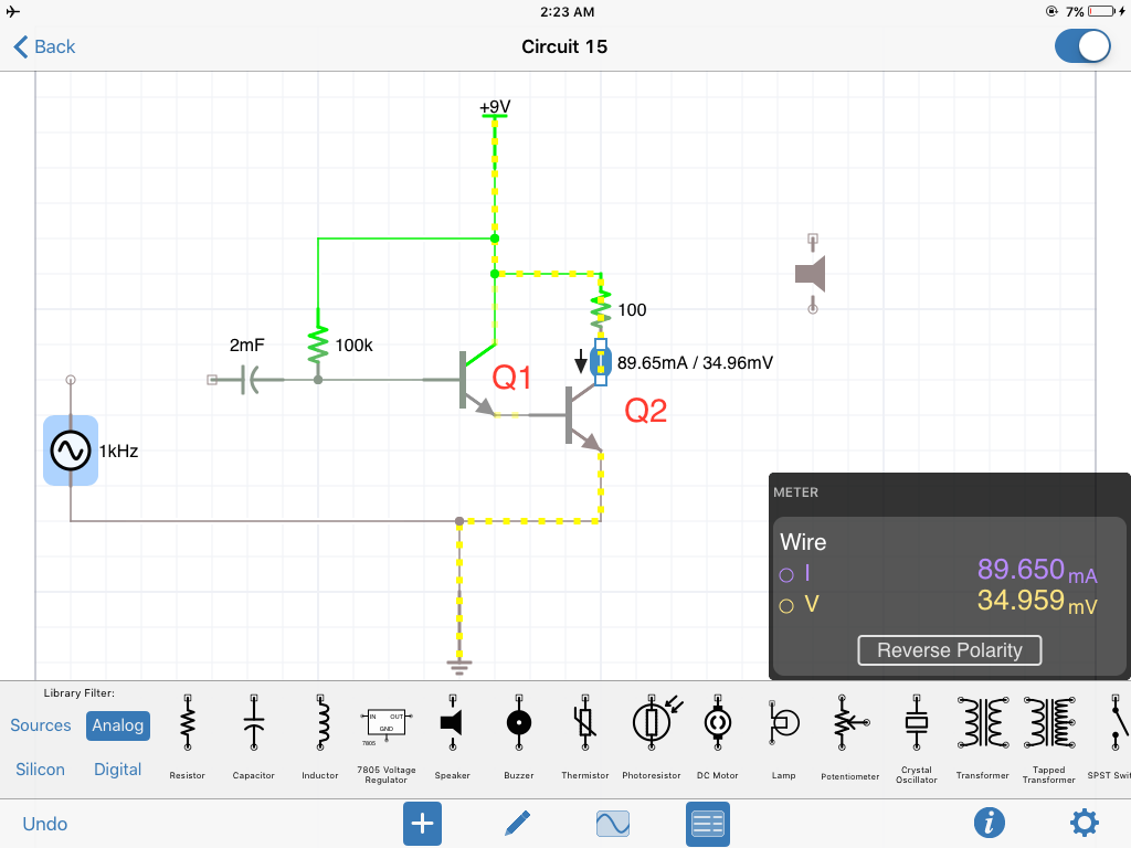
on the other hand the collect current on the second stage (the current that actually matters) is not Beta dependent and changes as collector resistor value changes, here's proof:

1ohms 10ohms 100ohms

Im stuck and can't figure out how to calculate it. any help is greatly appreciated

ok so here's an update apparently the last stage is at saturation... which means Ic=Vcc/Rc... so for Rc=10ohms Ic=9V/10ohms=roughly 900mA and for Rc=100ohms Ic=9V/100ohms=roughly 90mA ...

what I just cant understand is when Rc=1ohms Ic is not 9A but is Ib*Beta=3.5A

\$\endgroup\$
4
  • 1
    \$\begingroup\$ Hint: the maximum current occurs when transistor Q2 is in saturation. (Since you didn't bother putting designators on your schematic, you'll have to figure out for yourself which transistor I'm calling Q1 and which I'm calling Q2) \$\endgroup\$
    – The Photon
    Commented Mar 10, 2019 at 18:59
  • \$\begingroup\$ Ic is always dependent on hFE or Vbe and limited by Vcc/Rc , except your simulation is ideal and hFE actually reduces when Vcb drops to 1V or Vce=1.7 and reduces to ~ 10 to 20% of hFE at Vce(sat) \$\endgroup\$
    – D.A.S.
    Commented Mar 10, 2019 at 19:13
  • \$\begingroup\$ . If Vce in a transistor is 35mV @ 90mA , it means your simulation is wrong (too simple, fixed hFE) . this represents an Rce = 390 mOhm= 35mV/90mA when it should be + 1 diode drop (0.7V) + Ic*rCE= Vce(sat)=0.8V min @ 25'C diodes.com/assets/Datasheets/ds30047.pdf (Std) and super low Rce 38 mOhms diodes.com/assets/Datasheets/ZXTN04120HFF.pdf \$\endgroup\$
    – D.A.S.
    Commented Mar 10, 2019 at 19:32
  • \$\begingroup\$ tried in my other sim program current still changes \$\endgroup\$
    – PHO BOSS
    Commented Mar 10, 2019 at 20:01

1 Answer 1

0
\$\begingroup\$

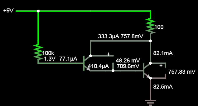
Using a Darlington transistor Vce(sat is higher)

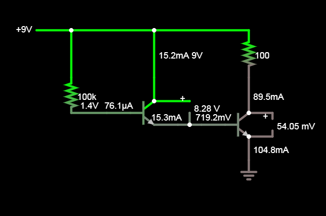
Then using two with isolated collectors the 1st does not saturate and the 2nd does which is why you concluded it was independent of hFE. ( Ic=Vcc/Rc) enter image description here

But a Darlington transistor ties both collectors together, so there is a Vbe drop added to the output.

enter image description here

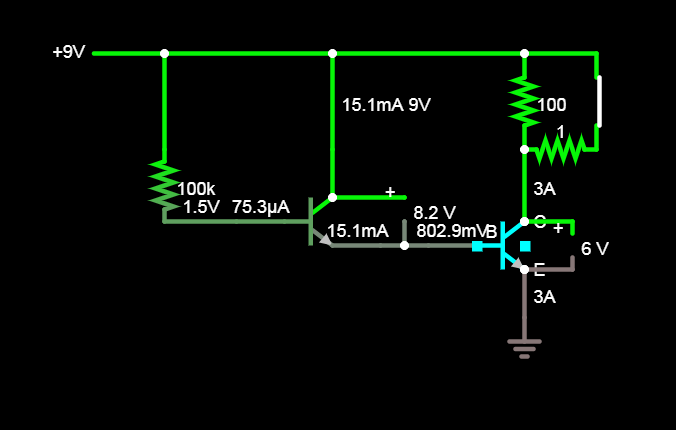
But in your 1 Ohm load case it is operating in linear mode limited by total Hfe

enter image description here

Note above uses hFE=200 for each 3A:15mA:75uA

They don't teach you this at schoole or show in datasheets

When a transistor saturates hFE reduces to ~ 10 to 20% of hFE max at Vce=Vce(sat) What they guarantee in datasheets is Vce(sat) @ Ic for Ic/Ib=10 to 20 per transistor.

So what Rb is needed to saturate 1 Ohm @ Vcc=9V near 8A \$Ib=\dfrac{8A}{h_{FE1}*(h_{FE}*10\text{%})}\$ =2mA so Rb= (9V-1.4V)/2mA = 3.8kohm

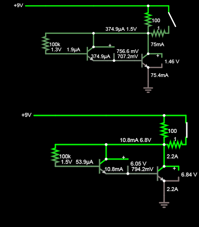
Other stuff, neg. feedback

Now see negative feedback situation.

enter image description here

\$\endgroup\$
13
  • \$\begingroup\$ so how can you predict Ic at Q2? \$\endgroup\$
    – PHO BOSS
    Commented Mar 10, 2019 at 20:10
  • \$\begingroup\$ from Vce . If Vce is >2V then use rated hFE, if Vce is saturated as with 100 Ohm load. then hFE drops to spec Vcesat Ic/Ib=10 meaning hFE=10 (worst case) but in reality it drops rapidly < Vce=2V to 10% which is near 10:1=Ic:Ib ratio at Vce(sat)=xx mV \$\endgroup\$
    – D.A.S.
    Commented Mar 10, 2019 at 20:14
  • \$\begingroup\$ Some datasheets differ diodes.com/assets/Datasheets/FMMT634.pdf on page 4 find Vce(at) and look at test conditions for Ic/Ib ratio sometimes 100 = two cascaded saturated transistors with 10x10=100 , sometimes 150:1 to 250:1 \$\endgroup\$
    – D.A.S.
    Commented Mar 10, 2019 at 20:17
  • \$\begingroup\$ So you check if Rc is current limiting or not from expect current then apply the corrected hFE or change Rb (base current overdrive as they used to call it) for saturation \$\endgroup\$
    – D.A.S.
    Commented Mar 10, 2019 at 20:19
  • \$\begingroup\$ Vce=Vc; Vc is dependent on Ic; Ic is dependent on beta; beta changes when Vce < 2V... is there even a way to solve for Ic through circuit analysis at this point? \$\endgroup\$
    – PHO BOSS
    Commented Mar 10, 2019 at 20:19

Your Answer

By clicking “Post Your Answer”, you agree to our terms of service and acknowledge you have read our privacy policy.

Not the answer you're looking for? Browse other questions tagged or ask your own question.