0
\$\begingroup\$

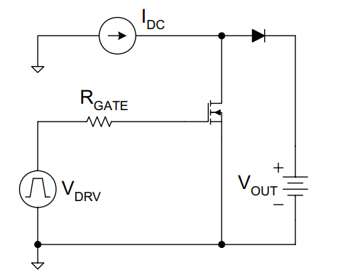
Consider the following circuit:

Source : Fundamentals of MOSFET and IGBT Gate Driver Circuits - TI

Image source: Simplified Clamped Inductive Switching Model - Figure 3 from "Fundamentals of MOSFET and IGBT Gate Drive Circuits by Texas Instruments"

I would like to improve the turn on speed of a MOSFET/IGBT. To do this, I think about reducing the Miller's plateau voltage in order to have a higher voltage between the driver (output high) and Vgs in order to charge Ciss more rapidly. And so reducing the Miller's plateau time.

However I do not know if it is possible to reduce the Miller's plateau voltage. The Miller's plateau begins when the drain voltage begins to decrease, i.e. when the diode stop conducting. So how to stop the conduction of the diode faster? A diode with low reverse recovery time would be the solution? Did I make a mistake? Is this wrong? Have you other recommendations/advice? More generally, is this a good idea to reduce the Miller's plateau?

\$\endgroup\$
3
  • \$\begingroup\$ But the plateau voltage is not constant and it will depend on the drain current. \$\endgroup\$
    – G36
    Commented Jan 1, 2020 at 16:34
  • \$\begingroup\$ Isn't the plateau voltage essentially equal to the threshold voltage? I.e., the point at which the charge in the channel begins to increase sharply, requiring a corresponding increase in gate charge. \$\endgroup\$
    – Dave Tweed
    Commented Jan 1, 2020 at 17:01
  • 1
    \$\begingroup\$ Thank you for your answers. The plateau voltage is theoritically constant in function of the time and is nearly constant in practice. It may depends on the drain current as the drain current is equal to the inductance current (source current) and the reverse recovery time depends on it. The miller pleateau is not equal to the thresold voltage. More informations can be found in the document "Fundamentals of MOSFET and IGBT gate drive circuit" written by TI \$\endgroup\$
    – Jess
    Commented Jan 1, 2020 at 17:49

1 Answer 1

0
\$\begingroup\$

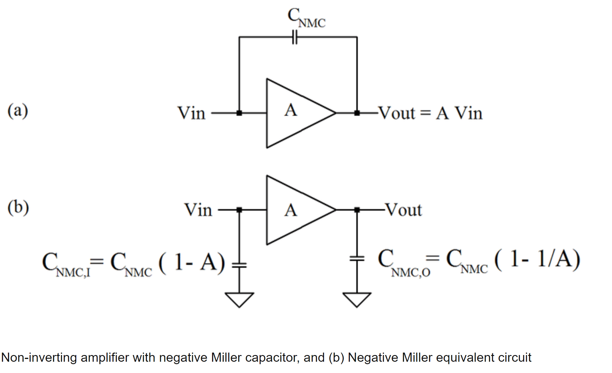
The Miller effect is due to having a capacitance across two points with a negative voltage gain between them.

[Intuitively you can think about one side of the cap getting pulled down by the gate-drain gain while the other side is pulled up by the gate driver, so you need to add the extra charge that the drain is trying to pull out.]

It multiplies the capacitance by ~ the voltage gain. So while you are transitioning through the linear region where the FET has gain you can't avoid it or change where it starts, you can only add more gate drive current to get through it faster.

From here:

enter image description here

\$\endgroup\$
4
  • \$\begingroup\$ Thank you for your answer. You say " one side of the cap getting pulled down by the gate-drain gain " Can I change the moment where the drain goes down ? This moment is not linked to the MOSFET but rather than to the diode ? Actually if I am wrong, I do not understand why it depends on the MOSFET. Or may be you want to say that Vgs_miller is equal to Vgs such that Vgs_miller*gm = Idc and then at this moment the miller's plateau begins, nevertheless the diode is now stop conducting and we have to wait the reverse recovery time of the diode... which can not be reduced :/ \$\endgroup\$
    – Jess
    Commented Jan 1, 2020 at 20:30
  • 1
    \$\begingroup\$ Yes, you're right, you may have to recover the diode before the drain can start to fall, but it's only after the drain starts to fall AFTER the diode is recovered that the Miller effect comes into play. So total switching time can be reduced by a faster or Schottky diode, but the miller plateau happens after the diode has recovered. \$\endgroup\$
    – John D
    Commented Jan 2, 2020 at 0:22
  • \$\begingroup\$ Thank you very much for your help ! And just to confirm Miller effect happens when the drain current is equal to Idc (current source, ie inductor), ie when vgs*gm = Idc ? And under this condition vgs is equal to the vgs_miller, ie where the miller's plateau begins ? So the Miller's plateau voltage level dépends on the transconductance gain of the Mosfet and the current Idc (inductor current) ? \$\endgroup\$
    – Jess
    Commented Jan 2, 2020 at 7:47
  • 1
    \$\begingroup\$ Yes, your last comment pretty much sums it up, except that the FET is pretty non-linear when it starts to turn on, so the value of gm (which is of course a linear small-signal approximation) at that point will not be the same as gm at higher drain currents. \$\endgroup\$
    – John D
    Commented Jan 2, 2020 at 15:33

Your Answer

By clicking “Post Your Answer”, you agree to our terms of service and acknowledge you have read our privacy policy.

Not the answer you're looking for? Browse other questions tagged or ask your own question.