1
\$\begingroup\$

I am reading the application note " Fundamentals of MOSFET and IGBT Gate Driver Circuits" written by Texas Instrument.

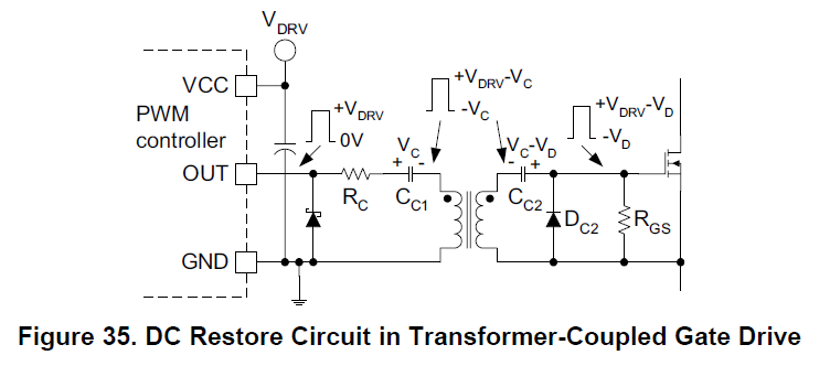
In order to control High Side MOSFET, the application note suggests to use this kind of circuit :

enter image description here

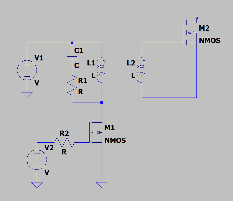
Why I just cannot use this kind of circuit ?

enter image description here

It seems simpler from my point … But this is probably not the case ?

enter image description here

Thank you very much !

\$\endgroup\$
1
  • 2
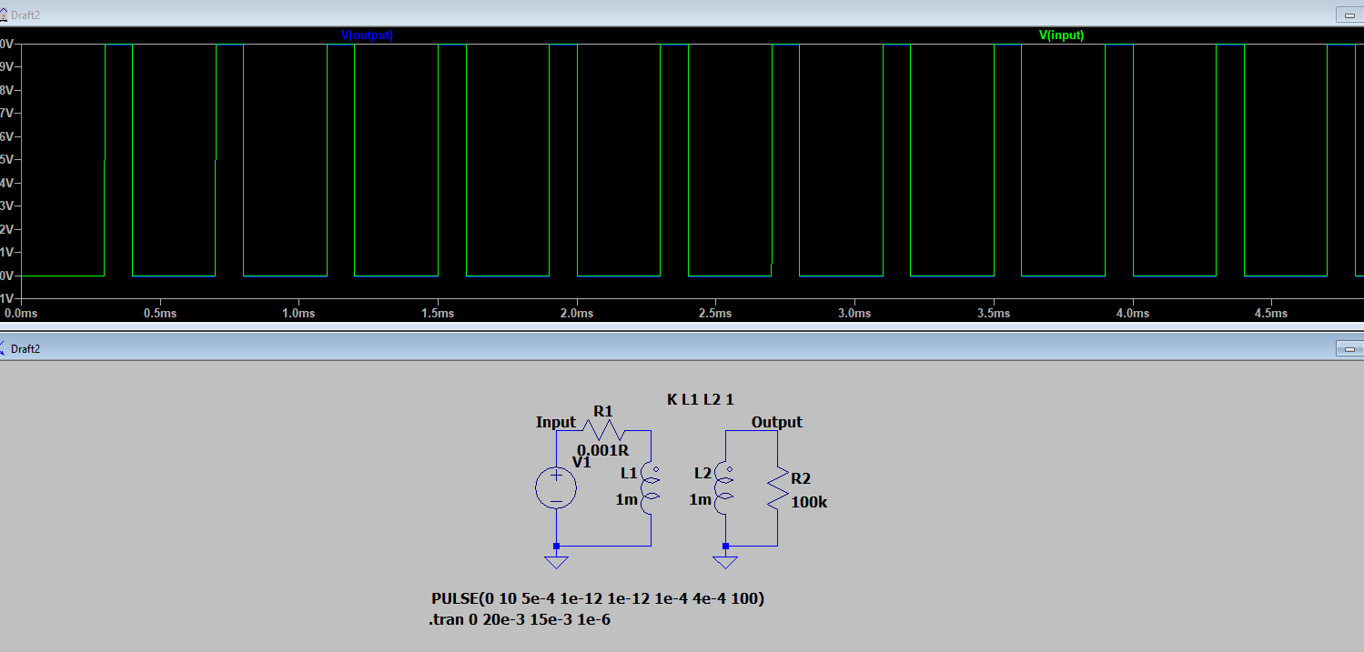
    \$\begingroup\$ You appear to have drawn your circuit in LTspice, have you simulated it as well? In the real world your NMOS might be damaged by voltage spikes that are not suppressed by diodes (which are present in TI's schematic). In your schematic L2 and M2 will resonate after the slopes of the pulse. That resonance isn't damped like in TI's schematic. \$\endgroup\$ Commented Jan 30, 2020 at 12:59

1 Answer 1

3
\$\begingroup\$

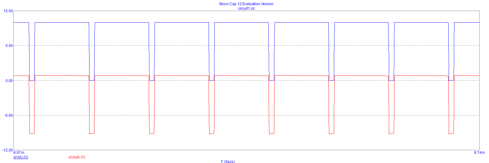
If you are controlling the pulse width but not using a DC restore circuit, it will mean that at a high value of duty cycle, the peak voltage from the transformer will not be enough to properly turn on the MOSFET.

Fact: the output of a transformer must have an average value of 0 volts and if the original pulse shape is 10 volts for 90% of the time, it will become 1 volt for 90% of the time after passing through the transformer: -

enter image description here

This is a simple simulation that shows what I mean. The input to the transformer goes between 0 volts and +10 volts (blue trace). It is capacitively coupled (1 uF) to the transformer primary. The red trace is the output of the transformer into a 1 kohm load.

\$\endgroup\$
14
  • 1
    \$\begingroup\$ No, it’s a tad subtler than that. Induced voltage is due to rate of change of flux and so if the average output voltage wasn’t zero it would imply an ever increasing magnitude of flux and that ain’t possible by a long way. \$\endgroup\$
    – Andy aka
    Commented Jan 30, 2020 at 21:09
  • 1
    \$\begingroup\$ It all comes from Faraday’s law of induction i.e. V equals N d(phi) by dt. \$\endgroup\$
    – Andy aka
    Commented Jan 30, 2020 at 21:11
  • 1
    \$\begingroup\$ I didn't comment on the primary flux in my answer because the basic problem (even if you were adequately driving the primary) is that the secondary CANNOT produce an average voltage that is not zero. To understand why the primary does not reset its flux requires more analysis but, nevertheless, even if it did reset its flux correctly, the secondary will always produce an average value of zero volts. \$\endgroup\$
    – Andy aka
    Commented Jan 31, 2020 at 8:38
  • 1
    \$\begingroup\$ Now try it with a more reasonable input resistor and look at maybe the 100th or 1000th cycle. Or just look at the current flowing into the primary and ask yourself when that current is going to settle down. \$\endgroup\$
    – Andy aka
    Commented Jan 31, 2020 at 20:30
  • 1
    \$\begingroup\$ You don’t really need to if you think about it a little; the average voltage applied to the primary is not zero hence, the current ramps up during the pulse and remains static during the off part of the input cycle. Along comes the next pulse and the current ramps up a bit more................... bang! \$\endgroup\$
    – Andy aka
    Commented Jan 31, 2020 at 21:32

Your Answer

By clicking “Post Your Answer”, you agree to our terms of service and acknowledge you have read our privacy policy.

Not the answer you're looking for? Browse other questions tagged or ask your own question.