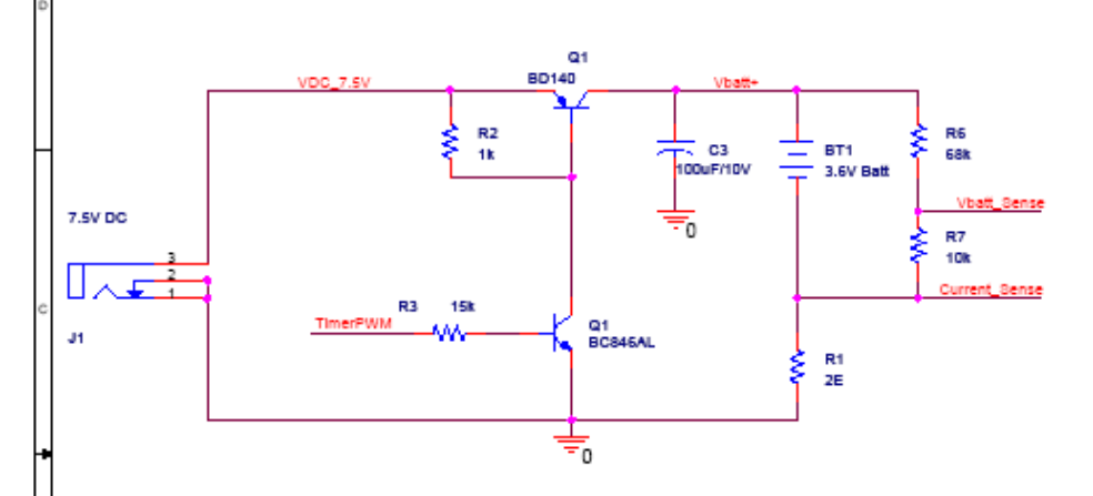
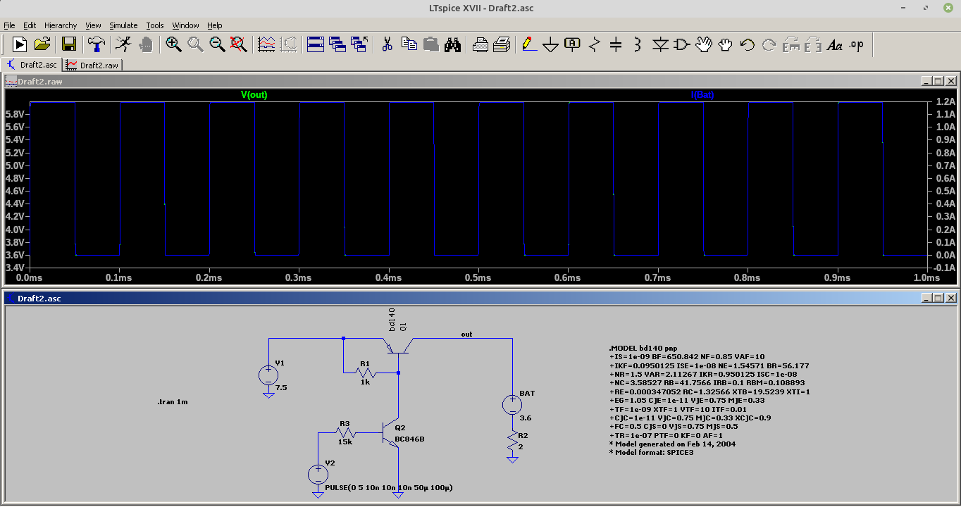
After doing some reading online, it seems that you can't really build a step-down converter with only a filtering capacitor and without an inductor. Because the losses occuring during charging of the capacitor would lead to low efficiency.
This type of DC-DC converter is known as a "charge pump". The capacitors in a charge pump are not for filtering, but for energy storage (unless it's an output capacitor, which is for filtering). In the simplest case, consider a voltage doubler: you charge a capacitor between power and ground, then disconnect the capacitor from ground, and connect the now-charged capacitor in series of the power supply.
Yes, efficiency at high current is much lower than a boost or buck converter, because charging or discharging a capacitor using a voltage source is fundamentally lossy, which limits their uses . Also, charge pump circuits are more suitable for doubling, having, or inverting a voltage than creating an arbitrarily regulated voltage.
But...
Efficiency is low, but total power consumption may be low enough that the designers just roll with it, as you said. The application note you linked is mostly a demo of a microcontroller than a practical power supply in production. In production, almost no one uses a microcontroller to reinvent a DC-DC converter.
It's still more efficient than a linear regulator, which may be good enough already. It's a middle-ground between a LDO and an inductor-based DC-DC.
For a low-current power supply (~ 100 mA), charge pumps can be fairly efficient for some applications. For example, at 20 mA, an old-school ICL7660 charge pump can be 90% efficient. A 3.3 V to 5 V charge pump using an MAX1595 controller is ~70% efficient at 125 mA.
See
 What makes this circuit work in that situation? Or maybe it acts as I described above - it has high losses, but the designers just roll with it?
