7
\$\begingroup\$

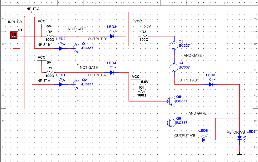
I am a very beginner in logic gates and electronic etc. I am trying to make an XOR gate only with the help of some basic components like transistors in the NI Multisim simulator. I have use AND and NOT gate circuits that I made and that were working alone but when I combine them all to make an XOR gate with those gate then it is not working at all. (My design is given below that I made in the simulator.)

Please help me fix this and increase my basic understanding of all these topics.

enter image description here

\$\endgroup\$
2
  • \$\begingroup\$ Can you describe in detail, what you mean by "not working at all". Is the final LED not lit at all or always lit or something else ? The currents from the base of the transistor may be flowing out from the emitters of the transistor and lighting the LED. \$\endgroup\$
    – AJN
    Commented Sep 13, 2020 at 12:03
  • \$\begingroup\$ After starting the simulation the the LED blink randomly few times and after that simulator throws an error \$\endgroup\$ Commented Sep 13, 2020 at 12:09

4 Answers 4

11
\$\begingroup\$

I can see at least four issues with your design.

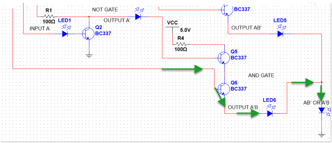
Firstly because you are using bipolar transistors your "and gate" doesn't actually implement an "AND" function, because the base-emitter junction of a bipolar transistor forms a diode. So if current flows in to the base of the lower transistor it will flow out of the emitter, no matter what the upper transistor is doing. You could fix that by using mosfets instead of bipolars but that would make other problems worse.

Secondly the "and gate" is not regenerative, the output voltage will always be lower than the input voltage and your LEDs drop more voltage. In some cases you can get away with non-regenerative gate designs, but it's easy for the volt drops to add up on you. A bipolar base-emitter junction drops about 0.7V, a LED somewere around 2V, mosfets are highly variable but nearly always more than a bipolar. It's not too hard to end up eating up all your voltage and ending up with none left.

Thirdly some of the paths through your circuit have NO current limiting. This is likely what is causing your simulation errors and if you tried to build the circuit for real may well result in fried components.

Fourthly many of your lines have nothing to pull them back down to ground when they are in the "off" state. Again you can sometimes get away with this but other times small leakage currents can cause big problems.


Start out by designing yourself NAND and NOR gates. Once you have NAND and NOR gates that behave sensibly (i.e. near full voltage on output for high, clean zero volts for low, output current capability much higher than input current requirements) you can then work out how to combine them into an XOR gate.

\$\endgroup\$
5
\$\begingroup\$

One problem is your terrible AND gates.

enter image description here

Figure 1. The base-emitter junction of the lower AND gate will always conduct and turn on the output.

You also have no current limiting resistors in that circuit.

You'll need to find a better AND implementation. Try a NAND followed by a NOT.

\$\endgroup\$
3
\$\begingroup\$

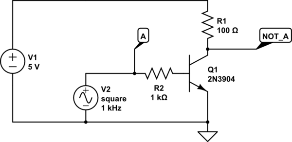
You've made a good start in thinking it through. It seems you are trying to implement resistor-transistor logic (RTL).

For the NOT gate, that should look something like this:

schematic

simulate this circuit – Schematic created using CircuitLab

Figure 1 – Resistor-transistor logic NOT gate.

Here is some background reading:

  1. Resistor-transistor logic (RTL)
  2. Transistor-transistor logic (TTL)
  3. Complimentary Metal Oxide Semiconductor (CMOS) logic
\$\endgroup\$
1
\$\begingroup\$

Usually, implementations of logic gates contain the inverted output of a function, and are then followed by an inverter.

However, the XOR [a^b = (a'*b)+(a*b')] function doesn't necessarily need an inverter, since some of its inputs are inverted anyways. Try using some inverters at the beginning to get these inverted inputs, and then implement the gate logic.

You might need to separate the gate voltage from the inputs' voltage, though, and instead of leaving it high-Z with the switch, try adding more switches to connect it to ground when not connected to Vcc.

\$\endgroup\$

Your Answer

By clicking “Post Your Answer”, you agree to our terms of service and acknowledge you have read our privacy policy.

Not the answer you're looking for? Browse other questions tagged or ask your own question.