1
\$\begingroup\$

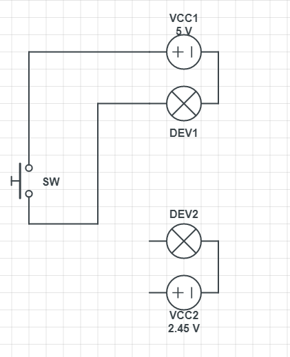
Currently, I have a push button (SW) controlling a device (DEV1). What I would like is to another device with the same push button (SW). I measured the voltage on DEV1's and DEV2's push button inputs, and I got 5v and 2.45v respectively.

Is it possible to have a single push button controlling both devices? What should I do with respect to the difference of voltage between DEV1 and DEV2?

enter image description here

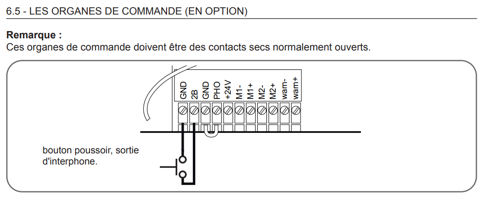
The devices are two swing gate motorizations. They both have push button input in the form of 2 screw connectors as shown below. Both devices are looking for dry contact.

enter image description here

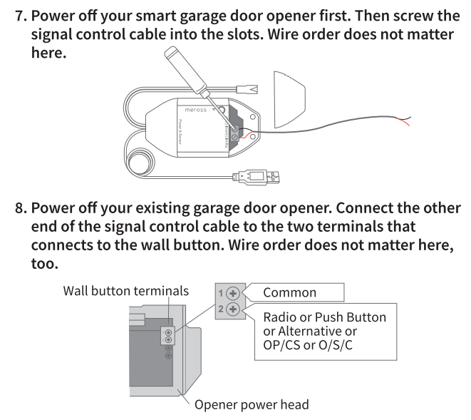
Furthermore, my ultimate setup will be replacing the single button with an output signal from Meross RSG100 WiFi garage opener kit as follows:

enter image description here

\$\endgroup\$
5
  • 2
    \$\begingroup\$ A warm welcome to the site. Can you change the switch? If so, use a DPST switch. That has two separate pairs of switching contacts in the one housing. I imagine you'll say you can't but if you can, it's the simplest way and gives you isolation between them. \$\endgroup\$
    – TonyM
    Commented Mar 3, 2021 at 15:11
  • \$\begingroup\$ Why not use an LDO off 5V to pwr 2.45V ? How much power? \$\endgroup\$
    – D.A.S.
    Commented Mar 3, 2021 at 15:15
  • \$\begingroup\$ If you can tie the grounds of the two circuits (are they both floating, or both referred to the same ground?) you could use the push button to drive two transistor switches. If you use BJTs and drive them into deep saturation you will lose about 0.1 V. \$\endgroup\$ Commented Mar 3, 2021 at 15:38
  • 2
    \$\begingroup\$ Imad - Welcome :-) Please can you edit the question & add more details about DEV1 and DEV2 and some real schematics about them. More details are needed about them, and how they are connected at the moment, in order to help get good quality answers. Photos of the devices &,wiring etc., although not a substitute for schematics, may also help readers. Thanks. \$\endgroup\$
    – SamGibson
    Commented Mar 3, 2021 at 16:30
  • \$\begingroup\$ @SamGibson - Thank you :) The devices are in reality two swing gate motorization. They both have push button input in the form of 2 screw connectors. Does that add any useful information? Thanks. \$\endgroup\$
    – Imad
    Commented Mar 8, 2021 at 9:41

2 Answers 2

2
\$\begingroup\$

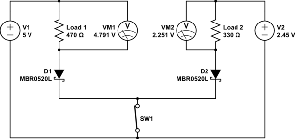
Depends on the devices but if they can tolerate a minor voltage change, you might try something like this. Components selection may need to change based on your specific equipment. I just put the volt meters in to illustrate the voltage on the load is somewhat lower than without the diodes. I don't recommend this method... But in a pinch...

schematic

simulate this circuit – Schematic created using CircuitLab

\$\endgroup\$
4
  • \$\begingroup\$ Hi, I have added more details to the description, do you think that this proposed solution could work without harm to the controlled devices? \$\endgroup\$
    – Imad
    Commented Mar 8, 2021 at 9:48
  • \$\begingroup\$ It's a little different situation than I had imagined, but yes, it should work. Those devices usually are looking for either a dry contact (button or relay) or an open collector electronic control. Using a diode with a switch will make it look like an electronic control. One issue here is that they need to share a ground. This isn't likely to be problematic but it could be equipment specific in a way that I cannot predict without knowing the specifics about each piece of equipment. Are you connecting two openers with one button? \$\endgroup\$ Commented Mar 8, 2021 at 10:19
  • \$\begingroup\$ Thanks for the explanation. Currently, they are connected to separate push buttons and it works fine. I wanted to be sure that connecting them to the button won't result in any harm. What could happen if they don't share the same ground? I know that both devices are looking for dry contact. \$\endgroup\$
    – Imad
    Commented Mar 8, 2021 at 10:46
  • \$\begingroup\$ This depends on the device. Some openers have opto-isolator inputs and you are just completing the path for the diode side. Other openers may use logic level inputs that have a pull-up resistor that makes them normally high and activated when you pull them low by grounding through the switch. I would guess that in most cases, there would not be a problem using four diodes to isolate the grounds as well. Maybe not ideal, but it would probably work. \$\endgroup\$ Commented Mar 8, 2021 at 10:59
0
\$\begingroup\$

Based on the fcc docs and internal photos the output of the wifi control module is a relay. And if you don't want to tie the two systems together the simplest option is to use another relay. No modification of the motors needed.

You can either modify the module to replace the existing relay with a DPDT one, or add a second one in parallel. You may have to look at the existing circuit to see how much current you have available.

Alternatively you can add an external relay. Any 3 to 5V dc dpdt relay with a battery pack or a USB power supply should be all you need. Wire between the module and your two motors. You can add a flyback diode for protection if needed.

\$\endgroup\$

Your Answer

By clicking “Post Your Answer”, you agree to our terms of service and acknowledge you have read our privacy policy.

Not the answer you're looking for? Browse other questions tagged or ask your own question.