2
\$\begingroup\$

I'm working with a system that requires a ~250-400 MHz modulation signal from 0 to 1.5 V (or -1.5 to 0 V) on an electro-optic modulator (EOM, Jenoptik AM635). I have a signal generator capable of producing the pulses that I need, but it only outputs in the range -0.35 to 0.35 V (can generate pulses with a DC offset). So I need to amplify the pk-pk signal as well as the DC bias, or introduce an appropriate DC bias somewhere else in the circuit. For reference, everything is 50 Ohm termination / input impedance.

Based on my (limited) understanding of RF electronics, I tried the following:

Signal generator (internal clock at 2 GHz) -> Mini-Circuits ZX60-43-S+ (RF Amplifier, 0.5-4000 MHz) -> Mini-Circuits ZFBT-4R2GW-FT+ (Bias Tee, 0.1-4100 MHz) -> EOM (50 Ohm load)

I then adjusted the output from the signal generator to get the correct pk-pk using the AC-coupled amplifier and added the necessary ~0.75 V DC bias on the bias tee. However, this doesn't work and I'm failing to understand why.

When I try to add the DC bias with a 50 Ohm terminated load my DC source hits its current limiter (set to 400 mA to avoid damaging the bias tee) and reaches maybe ~3 mV. When I just plug the output directly into an oscilloscope without a 50 Ohm terminator, the signal looks like what I want without any crazy current draw. I feel like there's something I'm missing here as I don't get why it's so different with and without the impedance matching at the oscilloscope.

Is there a way to modify this system with these components to achieve my desired result (square pulses at ~250-400 MHz that go from 0-1.5 V)? Would I be better served just using a wideband DC-coupled amplifier to begin with (e.g. a DCA-50-08)? Or is there some other option that would work better?

\$\endgroup\$

3 Answers 3

1
\$\begingroup\$

Knowing the difficulties of making an amplifier that amplifies DC exactly as much as 400 MHz, I'd say the approach of amplifying the AC signal and coupling in the DC bias is the right one.

I confirm this is the good approach, forget your bias T, go simpler so you can tweak the design, try things and SIMULATE! For that you can use LTSpice or QUCS STUDIO.

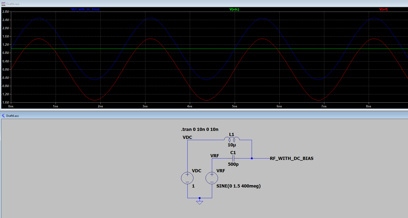
The following circuit should solve your problem. DC block capacitor, to safely generate your RF source without DC at your RF generator. You could use KSIM to find the good capacitor value, depending on your frequency.

Then choose a RF choke, for the inductor, to block any RF back into your DC voltage source.

EDIT : Simulated the whole thing, with arbitrary values that felt good to me (experience), so the theory of this thing is working. You could enhance this simulation by using component models created by the manufacturer for the capacitor and the inductor.

enter image description here

\$\endgroup\$
0
\$\begingroup\$

Knowing the difficulties of making an amplifier that amplifies DC exactly as much as 400 MHz, I'd say the approach of amplifying the AC signal and coupling in the DC bias is the right one.

Judging by your description of the problem, 3 mV meaning a DC current of 400 mA, we can deduct that you've basically have a DC short somewhere (something with a resistance of 3/400 Ω). Assuming your bias-tee is not strangely broken, my first suspicion would be that you're accidentally measuring the current through the circuit

DC source -> pin 3 (DC) of the bias tee -> pin 2 (DC + RF) of the bias tee -> DC source

instead of

DC source -> pin 3 (DC) of the bias tee -> pin 2 (DC + RF) of the bias tee -> 50Ω terminator -> DC source

If that's not the case, my second suspect would be the 50Ω terminator. Measure it alone with your DC current source (how much current flows through it at 1V?) or a multimeter (i.e. at DC) – is its DC resistance = 50Ω? Your terminator might be a short at DC, and only have 50Ω starting at, for example 100 MHz.

\$\endgroup\$
2
  • \$\begingroup\$ Thank you for the suggestions -- I'll try to look for a short / check the terminator on Monday when I'm back in lab. I'm pretty sure I connected everything in the correct order (it's all SMA cables, so I just plug stuff in basically). Is it possible that having both the amplifier and bias tee resting on a metal optical table is causing a short? Both cases are grounded, but not necessarily to the same point (through two separate power supplies). \$\endgroup\$
    – Zino
    Commented Aug 14, 2021 at 20:39
  • \$\begingroup\$ I don't believe it's a short in the terminator / my cabling (at least, as far as I can tell). The terminator shows 50 Ohms on a multimeter between the center and the casing. I'm still at a loss as to what's going on. \$\endgroup\$
    – Zino
    Commented Aug 17, 2021 at 19:12
0
\$\begingroup\$

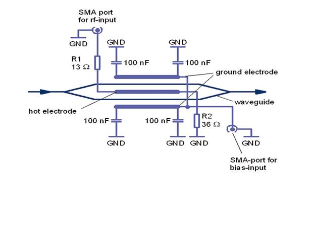
You can provide a bias to the other electrode of the EOM:

enter image description here There are application notes on the manufacturer's web-site.

The fact that it doesn't let you add a DC bias on the main input implies that there is a choke to ground that is not shown in the diagrams.

EOM Application note on separate bias

\$\endgroup\$
5
  • \$\begingroup\$ Right, so I'm a little confused as to how I actually make the connections they are recommending (the modulator I have is in Fig 6.3). Based on my reading of the diagram, they want me to put the modulator in a case, add some resistors / capacitors with paths to ground, and then apply the DC bias to the NEGATIVE side of the terminal. Is that how you would read the diagram as well? \$\endgroup\$
    – Zino
    Commented Aug 14, 2021 at 20:52
  • \$\begingroup\$ @Zino - I agree. \$\endgroup\$ Commented Aug 14, 2021 at 21:00
  • \$\begingroup\$ Is there an easy way to add components in line with SMA cables like what they want? For the components that go to the low side I can just solder to the outer casing, but for the "high" side I haven't seen a connector that is "easy" to connect to. \$\endgroup\$
    – Zino
    Commented Aug 14, 2021 at 21:15
  • \$\begingroup\$ @Zino - I can't think of an easy way offhand. Depending upon what frequency you are modulating at it looks tricky to ensure a good RF ground for the grounded electrode. I have never used that manufacturer but the EO modulators I have used made it easy to add the bias. \$\endgroup\$ Commented Aug 14, 2021 at 22:46
  • \$\begingroup\$ Thank you very much for the suggestions @Kevin White, I'll try to see if I can't work out their DC bias approach \$\endgroup\$
    – Zino
    Commented Aug 14, 2021 at 23:02

Your Answer

By clicking “Post Your Answer”, you agree to our terms of service and acknowledge you have read our privacy policy.

Not the answer you're looking for? Browse other questions tagged or ask your own question.