I have been working through very basic Verilog code examples at https://8bitworkshop.com (supports a book I am following). I understand there are a few good online options available and will pursue those at a later time.
My issue is that sometimes there is no access to the internet which renders the online simulation options moot. To help with this, IVerilog and GtkWave have been installed. IVerilog seems to do as expected and compiles modules. In my limited experience with the tool/toolchain, I have been using $display for limited terminal logging.
I would like to transition away from the online solutions but only seem to find the most basic examples of how to instrument simple designs.
Using the link above to the clock_divider.v module at 8bitworkshop can someone please explain to me how to instrument a testbench that will give me a .vcd file similar/exact to the output at 8bitworkbench? (See image below)
To save you time please find the source code for the clock_divider.v file following. Credit goes to the folks at https://8bitworkbench for the file.
module clock_divider(
  input clk,
  input reset,
  output reg clk_div2,
  output reg clk_div4,
  output reg clk_div8,
  output reg clk_div16
);

  always @(posedge clk)
    clk_div2 <= reset ? 0 : ~clk_div2;

  always @(posedge clk_div2)
    clk_div4 <= ~clk_div4;

  always @(posedge clk_div4)
    clk_div8 <= ~clk_div8;

  always @(posedge clk_div8)
    clk_div16 <= ~clk_div16;

endmodule
I have thrashed against the wall in terms of a suitable clock_divider_tb.v and apologize that I did not preserve previous code attempts. I am pretty frustrated in fact. Hoping someone can see where I am going wrong.
Following is the last iteration of clock_divider_tb.v before conceding defeat:
module clock_divider_tb;

reg RESET = 1'b0;

output wire CLK2;
output wire CLK4;
output wire CLK8;
output wire CLK16;

initial
  begin
    $dumpfile("clock_divider_tb.vcd");
    $dumpvars(0, clock_divider_tb);
    # 0 RESET = ~RESET;
    # 20 RESET = ~RESET;
    # 64 $finish;
  end

  reg CLK = 1'b0;
  always #1 CLK = ~CLK;

  clock_divider cd(.clk(CLK), .reset(RESET), .clk_div2(CLK2), .clk_div4(CLK4), .clk_div8(CLK8), .clk_div16(CLK16));

  initial
    $monitor(CLK,RESET,CLK2,CLK4,CLK8,CLK16);

endmodule
Update (Pre-post)
The last iteration of a testbench has been the closest (actually worked) result so far. All previous attempts returned a single $monitor time period only. Seems I needed to initialize the clock_divider module clk_div* outputs. My limited knowledge prevented me from realizing that 8bitworkbench was most likely initializing all scoped variables to the module to 0 before displaying the waves. Soon as I initialized the module clock registers the .vcd waveform(s) looked close. Oh so close.
Seems that now I am receiving a 1s (my timeframe) delay after RESET goes low before the clock divider waves seem to start. Please pardon the use of camera pictures as opposed to screenshots below to demonstrate the differences in waveforms I am receiving.
I have updated the clock_divider.v code to the following:
module clock_divider(
  input clk,
  input reset,
  output reg clk_div2,
  output reg clk_div4,
  output reg clk_div8,
  output reg clk_div16
);

  initial
    begin
      clk_div2 <= 0;
      clk_div4 <= 0;
      clk_div8 <= 0;
      clk_div16 <= 0;
    end

  always @(posedge clk)
    clk_div2 <= reset ? 0 : ~clk_div2;

  always @(posedge clk_div2)
    clk_div4 <= ~clk_div4;

  always @(posedge clk_div4)
    clk_div8 <= ~clk_div8;

  always @(posedge clk_div8)
    clk_div16 <= ~clk_div16;

emdmodule
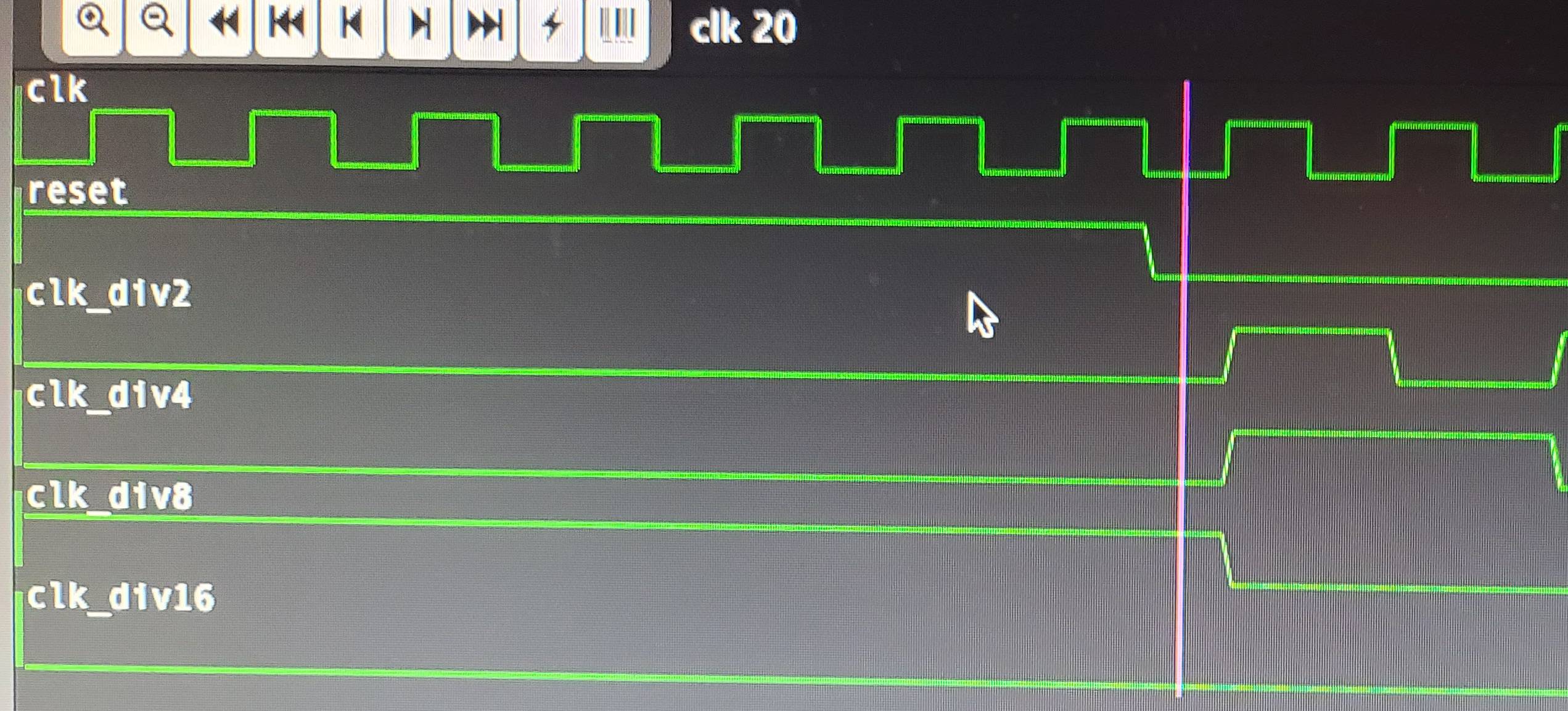
The following image is the Waveform result from 8BitWorkshop. Notice how everything times/aligns up with clk cycle 20, the period in which RESET is set to low as expected. This is what I am attempting to achieve with GtkWave.
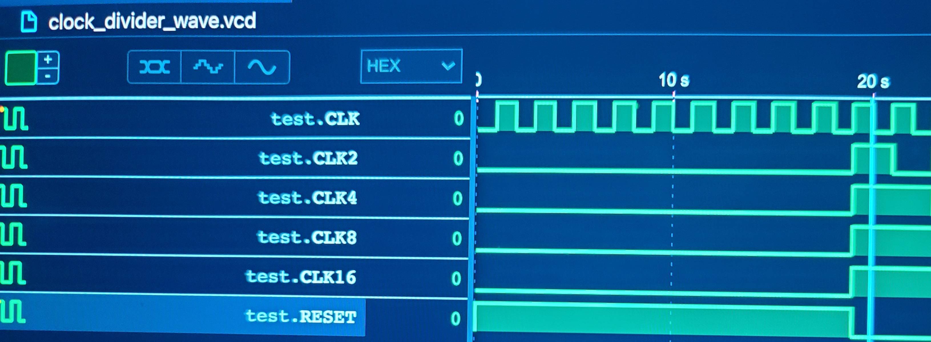
The following GtkWave image displays the .vcd file created using the testbench listed above. Notice how the clock dividers do not actually kick in until a full second after RESET is set low, unlike the 8BitWorkshop output does?
Just because it was not certain I was not looking at a rendering error with GtkWave I additionally installed the WaveTrace VSCode plugin just to verify the .vcd waveform. As it shows the problem is not with the rendering but my inability to instrument the module correctly.
The clock_divider module processes CLK signals on the posedge of the wave. Do I need to do something similar in the testbench file or is always #1 CLK =~CLK; a correct form of testbench clock to drive the module?
After trying to figure it out I need your help. Just what am I missing here? Any insight would be greatly appreciated.
TIA


 Thank you @Mitu Raj