1
\$\begingroup\$

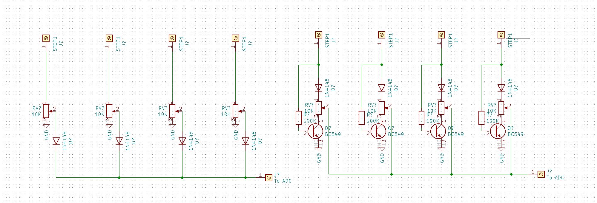
I am making a circuit that should read the values of many (4-16) potentiometers in a sequence, using one analog to digital converter. My approach is, as shown on the image below, to feed 5V in steps to each potentiometer, while the others are grounded (using a shift register.)

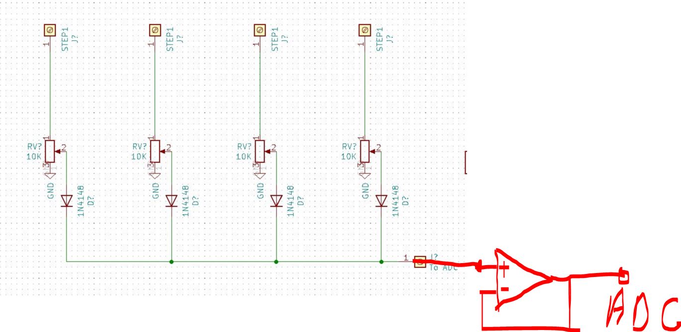
First I started with the classic layout, with one diode at the output of the potentiometers. This was giving me a lot of noise in the ADC output. I also tried to buffer the output with an opamp as a voltage follower. I thought that this will solve the issue, but to my surprise there was still a lot of noise.

Then I experimented with a layout like the image on the right. Again I am feeding 5V in steps to each potentiometer, while the others are grounded. This variant is giving me a lot more steady reading with almost zero noise.

I am not very experienced in eletronics though, and I don't know if this is a valid approach. I feel like it's a bit of a heresy. For now I am sticking with it though, because it works well, although the number of transistors required is high.

What do you people think, did I mess up the op amp buffer, or maybe loose wiring on the breadboard? I made sure my wiring was good but who knows. Does the schematic on the right look like a heresy to you?

enter image description here

enter image description here

I added the opamp buffer version to clarify what I did. Should this improve the noise in theory? For the record, I know about the way to do it with mux (have done it before), but I am trying this as an alternative, because it will benefit the device I am constructing in other ways(not relevant to the dicussion)

\$\endgroup\$
7
  • \$\begingroup\$ do you need the diodes on the one on the right? 100k tot he base is a bit low, might be better to use 1-10k to really pull the collector to ground at the same level accounting for minor transistor HFE variations. \$\endgroup\$
    – dandavis
    Commented Jan 29, 2022 at 22:04
  • \$\begingroup\$ @dandavis OP Is applying 5V to only one pot at a time while the others are have 0V applied. That's why the diodes are there. \$\endgroup\$
    – DKNguyen
    Commented Jan 29, 2022 at 22:12
  • \$\begingroup\$ you could use an open collector inverter IC, instead of discrete transistors, in the right circuit \$\endgroup\$
    – jsotola
    Commented Jan 29, 2022 at 22:56
  • 1
    \$\begingroup\$ I'd be inclined to use analogue switches, like a couple of 4051s. \$\endgroup\$
    – Ian Bland
    Commented Jan 29, 2022 at 23:11
  • \$\begingroup\$ Which DAC? If it does not have enough channels, why do you use it, or don't multiplex them yourself with a mux? Many MCUs also can have 16 analog input channels so maybe you are trying to use too small MCU for tje job. \$\endgroup\$
    – Justme
    Commented Jan 30, 2022 at 9:50

2 Answers 2

3
\$\begingroup\$

The circuit on the left is producing noise, and probably incorrect voltages to what you want, from the diodes. The diodes are not passing sufficient and consistent current into your ADC so their drop is varying through junction noise.

You don't specify part numbers for your ADC or the source of the row of drivers at your schematic top. I'll assume for now that this is all from a microcontroller with an internal ADC and GPIO pins driving the potentiometers.

The input impedance of your ADC will be very high and therefore draw almost no current from its input source, let's say 10 uA. That's borne out by the right-hand circuit producing almost no noise. That means the diodes in the left-hand circuit are passing a very tiny current. Putting in a op-amp buffer in will leave the same problem, as the op-amp also has a very high input impedance.

The underlying problem there is that you're seeing the diodes as 'magic one-way wires' and not designing based on their operating characteristics.

You should see the noise reduce if you connect, say, a 47K resistor across the ADC input pin and GND. This is not a solution, as it ruins the linear behaviour of your pot' and won't work properly when the pot' outputs low voltages, but it will demonstrate the point.

What you have in your right-hand circuit is not the neatest solution for it but at least your selected pot' provides strong resistances for the ADC pin to the voltage and to GND, while all other pot' paths are at very high resistance from the diodes and BJTs. That's why it has lower noise.

Proper analogue multiplexers would resolve the problem. There are plenty to choose from.

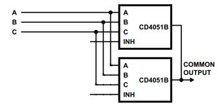
You don't specify any operating voltages. As an example of a mux, the long-standing CD4051 has 8 channels and a mux inhibit pin, INH i.e. an enable input. The below example circuit shows how to connect two to support 16 pot' inputs. Note that it won't operate at 3.3 V or pass rail-to-rail input voltages, it just illustrates the point. You'll need to work out your electrical requirements then choose a mux based on that.

enter image description here

(Modified form of Fig.25 from the Texas Instruments CD405xB datasheet (schs047i).

\$\endgroup\$
6
  • \$\begingroup\$ Thanks alot for the input! I was explaining it to myself something along those lines, that the current from the diodes is not sufficient, basically they turn the output of the pots into a very high impedance load. But my concern is why didn't it work with the opamp. Should it work in theory with the circuit on the left, and then buffered through the positive input of an opamp, configured as a voltage follower? This configuration should once again turn it into a low impedance load? The resistor to ground works, but it should be around 10k for good result, and the linearity is ruined \$\endgroup\$
    – KellerDev
    Commented Jan 30, 2022 at 7:40
  • \$\begingroup\$ I've extra-clarified the text but it's all explained there. Your op-amp also has a very high impedance, which you'll see when you look at the datasheet. Concentrate on "you're seeing the diodes as 'magic one-way wires' and not designing based on their operating characteristics" because that's the root of all understanding for you. The answer tells you a test resistor will only "demonstrate the point" because it will "ruin the linear behaviour of your pot'" so you're not surprised to see it do so. \$\endgroup\$
    – TonyM
    Commented Jan 30, 2022 at 9:36
  • \$\begingroup\$ Thanks again for your input. I am just trying to figure out the correct wayt to bring the high impedance from the diodes output to a low impedance for the ADC. I know the input of the opamp is highimpedance, but the output should be low impedance right? So maybe in this case again the noise comes from the high impedance out of the diodes and then is just amplified by the opamp. What is then the correct way to buffer the output of the diodes and keep the linearity of the potentiometers? \$\endgroup\$
    – KellerDev
    Commented Jan 30, 2022 at 11:11
  • \$\begingroup\$ @KellerDev, I think I see...are you trying to avoid tearing it up and starting again using analogue muxes? I appreciate your honesty about inexperience and admire you putting the work into trying an idea. But the whole pot-to-diode-to-ADC idea is dead in the water for accuracy, especially driven from I/O gates. Don't chase a poor solution and toy with it, it'll only get worse. The mux version is simple, will work and you'll get experience in a good solution, will teach you far more Rip it up and start again, you'll be glad you did :-) \$\endgroup\$
    – TonyM
    Commented Jan 30, 2022 at 13:23
  • \$\begingroup\$ Thanks again Sir/madam for the input. I appreciate your effort, but by insisting on the approach to do it with muxes you are changing the topic. I'm not sure why you are trying to shame me into doing it that way, but if this gives you some comfort, I have used muxes before and know how they operate. They are unfortunately less sutable for my goal due to the other functionality of the device I'm doing. \$\endgroup\$
    – KellerDev
    Commented Jan 30, 2022 at 14:22
1
\$\begingroup\$

You are using Arduino Nano and the AVR it has requires source impedance for ADC input to be less than 10k for best results. But as the pots are not directly connected to ADC input, it does not matter.

The diodes also conduct in one direction only, so the ADC input may be pushed higher via diodes at low impedance, but will have trouble going lower as the impedancr is very high, so the diodes and buffer will just make noise worse, and buffer it to ADC input.

\$\endgroup\$
2
  • \$\begingroup\$ Great, thanks for the input! Do you also have a solution for this problem? \$\endgroup\$
    – KellerDev
    Commented Jan 30, 2022 at 20:07
  • 1
    \$\begingroup\$ You only asked what's wrong with your circuit, not for solutions. Analog muxes were already recommended. Ditch the diodes and you don't even need an op-amp, as long as pots are below 40k in value, maybe go for 10k. \$\endgroup\$
    – Justme
    Commented Jan 30, 2022 at 20:11

Your Answer

By clicking “Post Your Answer”, you agree to our terms of service and acknowledge you have read our privacy policy.

Not the answer you're looking for? Browse other questions tagged or ask your own question.