3
\$\begingroup\$

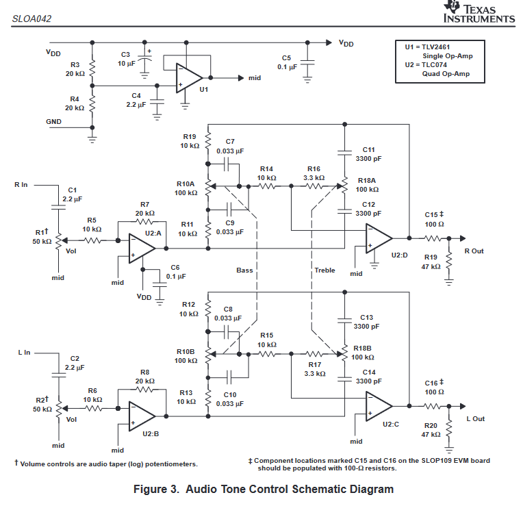
enter image description here

In this example, there is a "A TLV2461 operational amplifier IC is connected to provide a virtual ground for proper operation of the TLC074 from a single supply voltage."

I don´t quite understand the advantage of having a mid-bias point using a voltage follower (U1,) rather than having the same voltage divider (R3/R4) halving my voltage supply directly into U2.

I guess the difference will be the impedance: being 10KOhm with voltage divider, but much lower at U1 output in the order of 100Ohm.

How does this help?

Does it depend on the op-amp type I want to use?

\$\endgroup\$

2 Answers 2

12
\$\begingroup\$

The output of a voltage divider is not "rigid": It has an equivalent output resistance that is equal to the parallel combination of its constituent resistors. In this case, that'd be two 20kOhm resistors in parallel, which means that the voltage divider's output resistance is 10kOhm, as you already calculated.

A "virtual ground" with 10kOhm output resistance isn't particularly great. Any current flowing into or out of it will cause the virtual ground voltage to shift dramatically.

The voltage follower U1 fixes that: It buffers the virtual ground voltage (while not drawing any current from it) and provides the same voltage with a much lower output impedance (on the order of milliohms). This voltage doesn't vary even if some current is flowing into or out of it. It is a good voltage source.

Without the voltage follower, signal current flowing through potentiometers R1 and R2 would "contaminate" the virtual ground. This would allow audio signals to flow from one channel to the other channel via the virtual ground, ruining channel separation. (The left channel would bleed into the right channel, and vice-versa.) With the voltage follower, the virtual ground is unaffected by these currents, and the channels are properly separated.

If you didn't have R1 and R2 injecting a current into the virtual ground, you wouldn't need the voltage follower.

In short, the voltage follower is there because the output impedance of the virtual ground has to be much lower than the load connected to it.

As supercat mentioned in the comments, the virtual ground's voltage buffer (U1) can be eliminated by moving the input coupling capacitor behind the volume potentiometer (between pot and OpAmp), and connecting the volume pot to ground instead of mid. The low cut-off frequency of the coupling cap will vary a bit as the output impedance of the volume pot varies, but it shouldn't make too much of a difference.

\$\endgroup\$
4
  • \$\begingroup\$ Great explanation... but it would be even better if the full picture of currents was drawn... \$\endgroup\$ Commented Jan 19, 2023 at 15:40
  • \$\begingroup\$ A (very) minor nitpick: I believe the correct word to refer to a "rigid" voltage divider is stiff. \$\endgroup\$ Commented Jan 19, 2023 at 15:43
  • 1
    \$\begingroup\$ Could the need for a stiff mid-rail reference be eliminated by having the volume pots go to ground and putting the coupling cap between the pot and the op amp? \$\endgroup\$
    – supercat
    Commented Jan 19, 2023 at 20:07
  • \$\begingroup\$ @supercat Yes, absolutely! Good observation! \$\endgroup\$ Commented Jan 19, 2023 at 20:34
3
\$\begingroup\$

Here is a more unconventional explanation in five steps:

We assemble a voltage divider...

Figuratively speaking, the voltage divider consists of two resistors "pulling" the midpoint (virtual ground) with equal force but in the opposite direction - R3 "pulls" it up and R4 "pulls" it down.

But the voltage divider is weak...

The problem is that the resistors "pull weakly" (because they have relatively high resistance) and when another device starts to "pull" on that point, it gives in and starts to "move".

The straightforward solution

is to decrease both R3 and R4 resistances... but then the voltage divider will consume a lot of current.

The ingenious solution

can be found if we begin looking for a more clever solution. Thus we arrive at the idea that it is not necessary for both resistors to be of low resistance; only the "opposite" resistor should have low resistance. For example, if some device is "pulling" the virtual ground up, R4 should have low resistance to "pull" hard it down and v.v., if the device is "pulling" the virtual ground down, R3 should have low resistance to "pull" hard it up.

That is how we get to the idea that the resistors should be dynamic.

We implement the idea

This idea is implemented by the op-amp output stage which is inherently such a "dynamic voltage divider" consisting of two transistors (the so-called "push-pull" or complementary stage). An NPN pull-up transistor acts as a "dynamic R3" and a PNP pull-down transistor - as a "dynamic R4". This transistor pair can be thought as a "low-resistance copy" of the R3-R4 voltage divider.

Negative feedback point of view

The op-amp follower can be considered as a negative feedback system with constant input quantity (Vd/2 set by the R3-R4 voltage divider). Any device that injects/draws current into/from the op-amp output (virtual ground) is a disturbance that the op-amp tries to compensate for.

For example, if some device is "pulling" the virtual ground up, the lower PNP transistor "pulls" it down and v.v., if the device is "pulling" the virtual ground down, the upper NPN transistor "pulls" it up. As a result, the virtual ground does not "move".

\$\endgroup\$
6
  • \$\begingroup\$ Nothing in your answer is wrong, it just re-explains things OP already knows and states in the question, without answering the question. \$\endgroup\$
    – Ben Voigt
    Commented Jan 19, 2023 at 22:05
  • \$\begingroup\$ @Ben Voigt, I will only note that the distance from knowledge to understanding is too great. The purpose of my explanations is to shorten it. \$\endgroup\$ Commented Jan 19, 2023 at 23:07
  • 1
    \$\begingroup\$ The virtual ground opamp is mot needed with the Jfet-input opamps shown (they have extremely low input current) , but is needed if old opamps that have regular input transistors are used in the tone controls circuit. Maybe TI shows the un-needed opamp to sell more of the TLV2461 that is is expensive. \$\endgroup\$
    – Audioguru
    Commented Jan 20, 2023 at 1:01
  • \$\begingroup\$ Please use the voting system for incorrect answers \$\endgroup\$
    – Voltage Spike
    Commented Jan 20, 2023 at 7:39
  • \$\begingroup\$ every time you talk about voltages "moving" I am going to remember this terrible animation: electronics.stackexchange.com/questions/221253/… \$\endgroup\$ Commented Jan 20, 2023 at 12:46

Your Answer

By clicking “Post Your Answer”, you agree to our terms of service and acknowledge you have read our privacy policy.

Not the answer you're looking for? Browse other questions tagged or ask your own question.