1
\$\begingroup\$

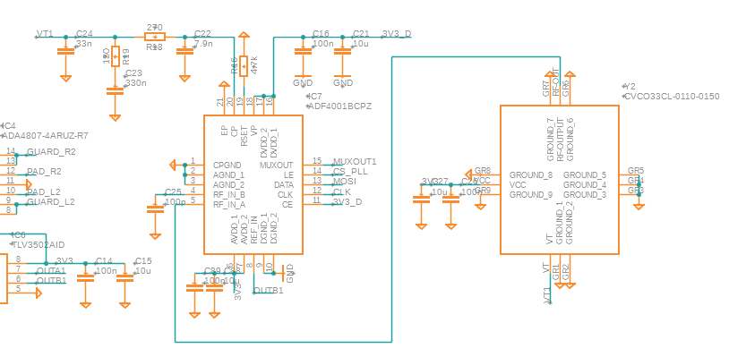
I designed and tested a PCB with a PLL circuit. The goal is to lock on the reference signal which is a square wave. The problem I am having is that the signal of the N-counter shows no response, just 0V dc. The N-counter signal is measured via the MUXOUT of the ADF4001. I can correctly measure the R-counter with the MUXOUT.

The VCO I am using is the CVCO33CL-0110-0150. I have measured the VCO signal with a scope. It is about 1VPP. According to the spec sheet the VCO delivers -3 dBm to +3 dBm. The ADF4001 specifies an RF input sensitivity of -10 dBm to 0 dBm. I got this working before with a higher power VCO with 5 V supply (CVCO55CL-0060-0110, output power 5 dBm to 12 dBm). To be honest, I am not quite sure what these specs mean and if it is ok or not. Also I've been looking into whether I should do more effort in matching the impedance of the line (it is only a short line on the PCB of 5 mm). But I figured that for a 100 MHz signal this should not be too much of a problem.

The register settings:

cp = 7
muxout = 1
r0 = (cp << 18) + (cp << 15) + (1 << 7) + (muxout << 4) + 2
self.devA.spiMaster_SingleWrite(struct.pack(">I", r0)[1:], True)
# set R
ldp = 1
R  = 1
r0 = (ldp << 20) + (R << 2)
self.devA.spiMaster_SingleWrite(struct.pack(">I", r0)[1:], True)
# set N
N = 18
r0 = (N << 8) + 1
self.devA.spiMaster_SingleWrite(struct.pack(">I", r0)[1:], True)

The loop filter is bandwidth 10 kHz.

Link to data sheets:

enter image description here

\$\endgroup\$
0

2 Answers 2

0
\$\begingroup\$

You're probably OK with the impedance matching between the VCO and the RF input port. When you say the MUXOUT with the N divider is death, what do you mean? Are you not seeing a signal there at all? with Vtune limited to 3.3V, you're not going to be able to get above 150 MHz or so, the tuning voltage on the VCO is 0 < VTune < 5Vdc. My initial thought is that you're not setting the registers correctly, so I'd double check that you're setting that correctly.

\$\endgroup\$
2
  • \$\begingroup\$ Thanks. With the N divider being death I mean there is no signal, just 0Vdc. It should work fine with a Vtune voltage lower than 3.3V right. I should still see a signal, only with lower frequency than with Vtune is 5V. I can play around a bit more with the registers, but it used to work when I was using 5V vcc. \$\endgroup\$
    – Chris
    Commented May 26, 2023 at 6:04
  • \$\begingroup\$ break the loop at the loop filter, apply ~ 1.5V at the VCO tune port, and see if you get a ÷N signal at the output. That gives you a "known signal" at the RF input port, and you should see a mux out at the appropriate frequency. I've played with an AFD4002, and that pulse is very, very short, so get your oscope triggered on the ÷R signal, which is wider, then switch to ÷N and see if you see that signal. \$\endgroup\$
    – rfdave
    Commented May 31, 2023 at 2:00
0
\$\begingroup\$

Why no DC blocking cap between the VCO and the ADF4001? It is worth checking that the CVC033 DC output impedance is not upsetting the input bias of the ADF4001. This would certainly produce these symptoms - works with high signal levels, fails with lower ones.

\$\endgroup\$
2
  • \$\begingroup\$ Thanks. That is something I can try. Would you also recommend to add a 50ohm resistor to ground then? \$\endgroup\$
    – Chris
    Commented May 26, 2023 at 6:02
  • \$\begingroup\$ Only if the VCO manuf recommends it, or if the signal level is too high. \$\endgroup\$
    – Tesla23
    Commented May 26, 2023 at 7:49

Your Answer

By clicking “Post Your Answer”, you agree to our terms of service and acknowledge you have read our privacy policy.

Not the answer you're looking for? Browse other questions tagged or ask your own question.