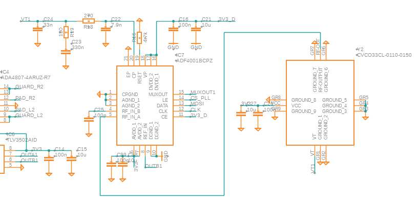
I designed and tested a PCB with a PLL circuit. The goal is to lock on the reference signal which is a square wave. The problem I am having is that the signal of the N-counter shows no response, just 0V dc. The N-counter signal is measured via the MUXOUT of the ADF4001. I can correctly measure the R-counter with the MUXOUT.
The VCO I am using is the CVCO33CL-0110-0150. I have measured the VCO signal with a scope. It is about 1VPP. According to the spec sheet the VCO delivers -3 dBm to +3 dBm. The ADF4001 specifies an RF input sensitivity of -10 dBm to 0 dBm. I got this working before with a higher power VCO with 5 V supply (CVCO55CL-0060-0110, output power 5 dBm to 12 dBm). To be honest, I am not quite sure what these specs mean and if it is ok or not. Also I've been looking into whether I should do more effort in matching the impedance of the line (it is only a short line on the PCB of 5 mm). But I figured that for a 100 MHz signal this should not be too much of a problem.
The register settings:
cp = 7
muxout = 1
r0 = (cp << 18) + (cp << 15) + (1 << 7) + (muxout << 4) + 2
self.devA.spiMaster_SingleWrite(struct.pack(">I", r0)[1:], True)
# set R
ldp = 1
R  = 1
r0 = (ldp << 20) + (R << 2)
self.devA.spiMaster_SingleWrite(struct.pack(">I", r0)[1:], True)
# set N
N = 18
r0 = (N << 8) + 1
self.devA.spiMaster_SingleWrite(struct.pack(">I", r0)[1:], True)
The loop filter is bandwidth 10 kHz.
Link to data sheets:

