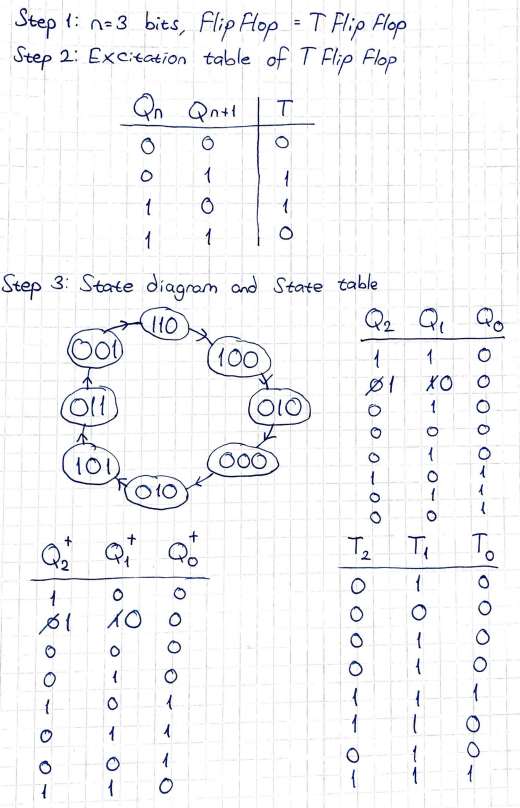
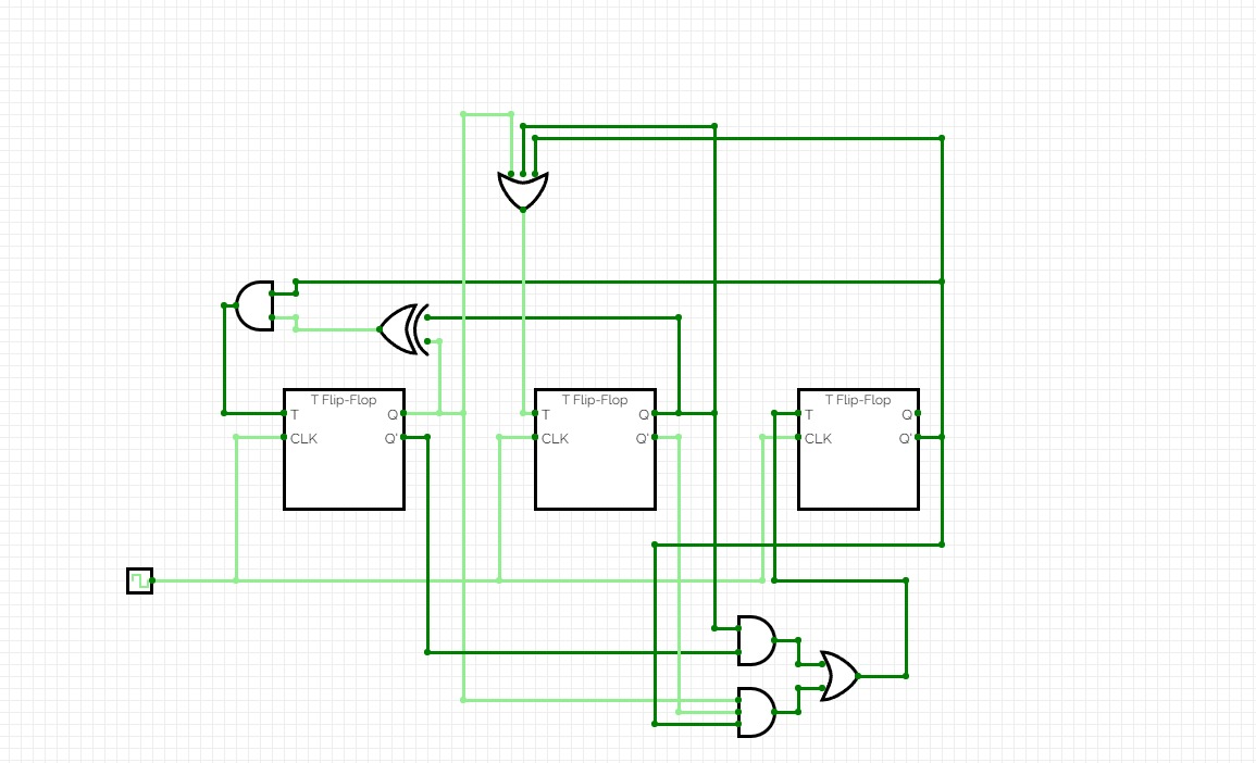
I'm trying to design a counter circuit that counts 6 → 4 → 2 → 0 → 2 → 5 → 3 → 1 using T flip flops and I haven't been able to achieve it. I tried the steps below and designed the circuit below in CircuitVerse, but it doesn't work properly. Where am I making a mistake? Some people have pointed out I needed to use a Mealy machine, but I haven't been able to understand why.
1 Answer
initial state, general comments
One of the first issues encountered in a problem like this is the initial state, itself. In simulators, FF's usually start up with \$Q=0\$ and \$\overline{Q}=1\$.
In some physical reality cases, there's no way to know the power-up state. In such cases, am asynchronous CLR and/or SET pin is needed. (Or some other mechanism to delay use until the initial states can be established.) Here, I'd attach a power-on reset circuit so that the FFs are held in either CLR or SET state while the power supply becomes stable, releasing that line only after the supply is known-stable.
But in these purposes I'll assume that at the beginning \$Q=0\$ and \$\overline{Q}=1\$.
initial state assumptions
In this case, I'll take it that each T FF powers up with \$Q=0\$ and \$\overline{Q}=1\$.
Antonio51 brings up an important point: state 2 comes up twice and it doesn't transition to the same next state. So this means you need an additional T FF to distinguish one from the other, or four T FFs not three.
It doesn't matter what it's initial state is, you can work with it either way. But for simplicity's sake, let's assume that the first state \$2\$ uses the added T FF as \$Q=0\$ and \$\overline{Q}=1\$ and the second state \$2\$ uses it, oppositely.
This distinguishing bit can be placed anywhere you want. Doesn't matter. But I'll make it the higher-order bit of the sequence, again for simplicity's sake.
Since you want the initial state to be \$6\$ this just means that you set things up so that your actual output is taken as \$\overline{Q_2}\:\overline{Q_1}\:Q_0\$.
To get the desired result, 6 → 4 → 2 → 0 → 2 → 5 → 3 → 1, the states will be \$0\$, \$2\$, \$4\$, \$6\$, \$12\$, \$3\$, \$5\$, and \$7\$.
Take \$\overline{Q_2}\$, \$\overline{Q_1}\$, and \$Q_0\$ as the counter outputs.
FF options
The following is just a note. You've already said that you want T FF. Granted.
But to be pedantic it doesn't hurt to keep in mind there are at least these options for FFs:
$$\begin{array}{c|c|c} \text{Transition} & \text{JK FF} & \text{T FF} & \text{D FF}\\\hline {\begin{smallmatrix}\begin{array}{c} \text{start }\to\text{ end}\\\\ 0 \quad \to \quad 0\\ 1 \quad \to \quad 1\\ 0 \quad \to \quad 1\\ 1 \quad \to \quad 0 \end{array}\end{smallmatrix}} & {\begin{smallmatrix}\begin{array}{cc} J & K \\\\ 0&x\\ x&0\\ 1&x\\ x&1 \end{array}\end{smallmatrix}} & {\begin{smallmatrix}\begin{array}{c} T\\\\ 0\\ 0\\ 1\\ 1 \end{array}\end{smallmatrix}} & {\begin{smallmatrix}\begin{array}{c} D\\\\ 0\\ 1\\ 1\\ 0 \end{array}\end{smallmatrix}} \end{array}$$
counter table
The table I see for this problem is:
$$\begin{array}{c|c} \text{States} & \text{FF Inputs}\\\hline\\ {\begin{smallmatrix}\begin{array}{cccc} Q_D & Q_C & Q_B & Q_A\\ \vphantom{\left.\overbrace{\begin{array}{ccc}J & K & T & D\end{array} } \right.}\\ 0&0&0&0\\ 0&0&1&0\\ 0&1&0&0\\ 0&1&1&0\\ 1&1&0&0\\ 0&0&1&1\\ 0&1&0&1\\ 0&1&1&1\\\\ 0&0&0&1\\ 1&0&0&0\\ 1&0&0&1\\ 1&0&1&0\\ 1&0&1&1\\ 1&1&0&1\\ 1&1&1&0\\ 1&1&1&1 \end{array}\end{smallmatrix}} & {\begin{smallmatrix}\begin{array}{cccc} Q_D & Q_C & Q_B & Q_A\\ \left.\overbrace{\begin{array}{cccc}T\\ 0\\ 0\\ 0\\ 1\\ 1\\ 0\\ 0\\ 0\\\\ x\\ x\\ x\\ x\\ x\\ x\\ x\\ x \end{array} } \right. & \left.\overbrace{\begin{array}{cccc}T\\ 0\\ 1\\ 0\\ 0\\ 1\\ 1\\ 0\\ 1\\\\ x\\ x\\ x\\ x\\ x\\ x\\ x\\ x \end{array} } \right. & \left.\overbrace{\begin{array}{cccc}T\\ 1\\ 1\\ 1\\ 1\\ 1\\ 1\\ 1\\ 1\\\\ x\\ x\\ x\\ x\\ x\\ x\\ x\\ x \end{array} } \right. & \left.\overbrace{\begin{array}{cccc}T\\ 0\\ 0\\ 0\\ 0\\ 1\\ 0\\ 0\\ 1\\\\ x\\ x\\ x\\ x\\ x\\ x\\ x\\ x \end{array} } \right. \end{array}\end{smallmatrix}} \end{array}$$
k-maps
I'm not going to draw out the k-maps. You can take the above table and generate those, if you like. And it's good practice.
However, you can also readily plug any part of the above information into Steve Rickman's Logic Friday program (the latest version I have is 1.1.4.) It will minimize the logical algebra. If you do your own k-maps, verifying your findings using Logic Friday makes sense.
When using Logic Friday, also make sure that you select its minimize option as shown below:
From there, you should be able to set up the logic for your T FFs.
Don't forget that your output is not taken from the \$Q\$ outputs the lower-order three T FFs. Take \$\overline{Q_2}\$, \$\overline{Q_1}\$, and \$Q_0\$ as the counter outputs!


2output you want to transition to0and sometimes to5. So you'll need to keep track of some additional state aside from just the output value. \$\endgroup\$2's isn't supposed to be a7? \$\endgroup\$