1
\$\begingroup\$

I need to do a voltage conversion to control a servomotor.

I need to convert a pwm signal that ranges from 0V to + 3.3V into an amplified signal that ranges from -10V to + 10V.

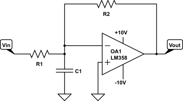
I thought about doing this with the use of an operational amplifier (as in the circuit below).

However, I can't get the correct Vout signal, just a voltage ranging from 0V to + 10V.

Is there another way to do this conversion?

schematic

simulate this circuit – Schematic created using CircuitLab

\$\endgroup\$

2 Answers 2

2
\$\begingroup\$

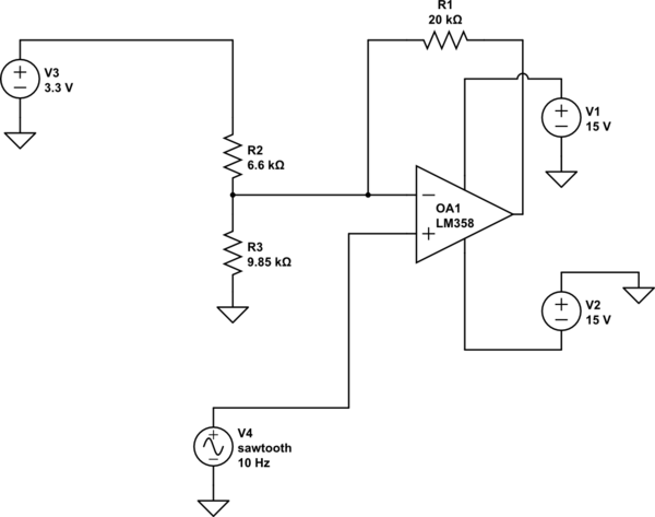
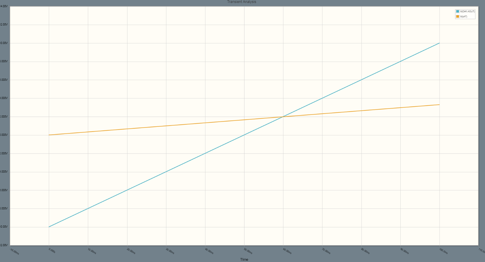
This circuit will do it, also it has a high-impedance input so it will not load your (required) low pass filter.

schematic

simulate this circuit – Schematic created using CircuitLab enter image description here

\$\endgroup\$
2
  • \$\begingroup\$ Thanks, could you tell me where I find the equations to determine the resistors? \$\endgroup\$ Commented May 18, 2020 at 20:32
  • \$\begingroup\$ Ohm's law and equating the op-amp input voltages. One of the resistors is arbitrary, the ratios are not, given the gain and offset (and the reference voltage, here 3.3V). Of course if you make the resistors too high or too low the circuit won't work well. I picked 20K for R1. That fixes R2||R3 from the gain, and the value of R2 falls out from the offset requirement & reference voltage. \$\endgroup\$ Commented May 18, 2020 at 20:43
2
\$\begingroup\$

This circuit uses E24 series resistors.
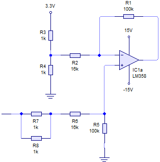
Level converter

This circuit is basically a subtractor. It subtracts the Thevenin equivalent voltage at the input to the upper branch (R2/R3/R4 junction) from the circuit's actual input voltage and multiplies the result by the gain.

The requirements of the circuit are to provide -10V to +10V output for 0V to +3.3V input.

When designing a level shifter like this the first step is to ascertain the required gain which is:

20/3.3 = 6.0606

Then it's a matter of considering many combinations of pairs of E24 series resister values until a ratio is found which will give the required gain. It greatly helps if you know by memory the values in the E24 series then you can play around on a calculator for 5 or 10 minutes.I found the values of 100k and 16.5k give a gain of exactly 6.0606 where the 16.5k is made up of 16k and 2 x 1k in parallel.

The gain of this subtractor circuit is given by R1/(R2 + R3//R4) but the ratio in the other branch should be exactly the same = R5/(R6 + R7//R8).

Now, in a range shifter the point at the bottom end of R5 should be connected to the voltage at the centre of the output swing which is 0V in this case. The Thevenin equivalent voltage at the R2/R3/R4 junction should always be equal to the voltage which is the centre of the input swing which is 1.65V in this case.

By making R3 & R4 both equal to 1k I managed to get the correct thevenin equivalent resistance (500R) and the correct Thevenin equivalent voltage (1.65V).

The op amp is powered from +&- 15V which easily allows the output to swing to +&- 10V.
\$\endgroup\$
3
  • \$\begingroup\$ Your answer should contain some explanations rather than just firing off the solution exam-style. It should be written clearly enough to teach future readers. Please can you edit it and greatly improve it. Thanks. \$\endgroup\$
    – TonyM
    Commented May 19, 2020 at 13:05
  • \$\begingroup\$ @TonyM Hope that helps. \$\endgroup\$
    – user173271
    Commented May 19, 2020 at 15:17
  • \$\begingroup\$ Thanks James, excellent and upvoted :-) \$\endgroup\$
    – TonyM
    Commented May 19, 2020 at 16:59

Your Answer

By clicking “Post Your Answer”, you agree to our terms of service and acknowledge you have read our privacy policy.

Not the answer you're looking for? Browse other questions tagged or ask your own question.