This circuit uses E24 series resistors.

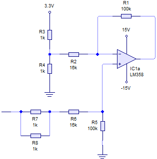
This circuit is basically a subtractor. It subtracts the Thevenin equivalent voltage at the input to the upper branch (R2/R3/R4 junction) from the circuit's actual input voltage and multiplies the result by the gain.
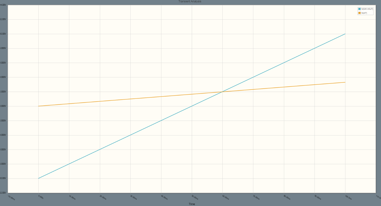
The requirements of the circuit are to provide -10V to +10V output for 0V to +3.3V input.
When designing a level shifter like this the first step is to ascertain the required gain which is:
20/3.3 = 6.0606
Then it's a matter of considering many combinations of pairs of E24 series resister values until a ratio is found which will give the required gain. It greatly helps if you know by memory the values in the E24 series then you can play around on a calculator for 5 or 10 minutes.I found the values of 100k and 16.5k give a gain of exactly 6.0606 where the 16.5k is made up of 16k and 2 x 1k in parallel.
The gain of this subtractor circuit is given by R1/(R2 + R3//R4) but the ratio in the other branch should be exactly the same = R5/(R6 + R7//R8).
Now, in a range shifter the point at the bottom end of R5 should be connected to the voltage at the centre of the output swing which is 0V in this case. The Thevenin equivalent voltage at the R2/R3/R4 junction should always be equal to the voltage which is the centre of the input swing which is 1.65V in this case.
By making R3 & R4 both equal to 1k I managed to get the correct thevenin equivalent resistance (500R) and the correct Thevenin equivalent voltage (1.65V).
The op amp is powered from +&- 15V which easily allows the output to swing to +&- 10V.


