Question
I'm trying to make a component model for the LH0063 single ended line driver in LTspice... The propagation delay is the dominant parameter for the frequency response but I'm having a hard time modeling it.
I'm using the 'Universalopamp2' component as a voltage follower... I see there are different levels(versions) to this component. Is there a way I can configure this model's parameters to simulate the propagation delay?
About the part
from the datasheet:
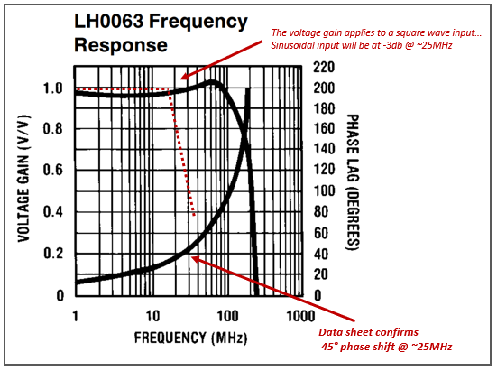
- Bandwidth: 100MHz
- SlewRate: 6000V/us
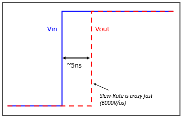
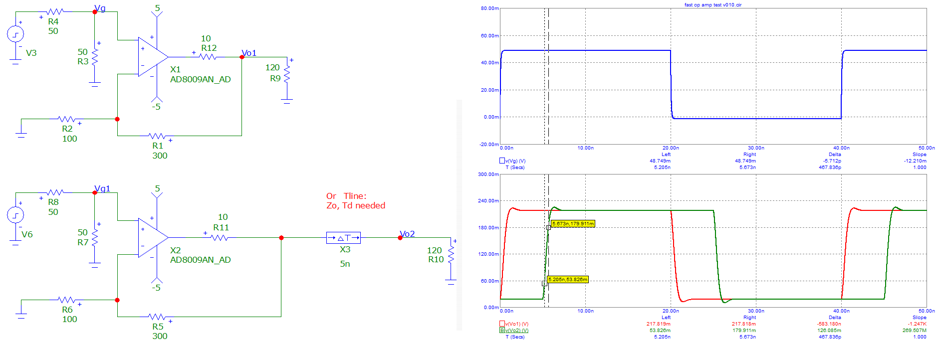
From bench testing, the Slewrate is real but the Bandwidth is not... The propagation delay attenuates the signal. The part has a propagation delay of ~5ns .
- An input square-wave signal of 25MHz(Tp=40ns), will be shifted by 5ns (45degress phase shift).
- An input sine-wave signal of 25MHz(Tp=40ns), will be shifted 45degress and will be attenuated by -3db.
Looks like this on the bench:
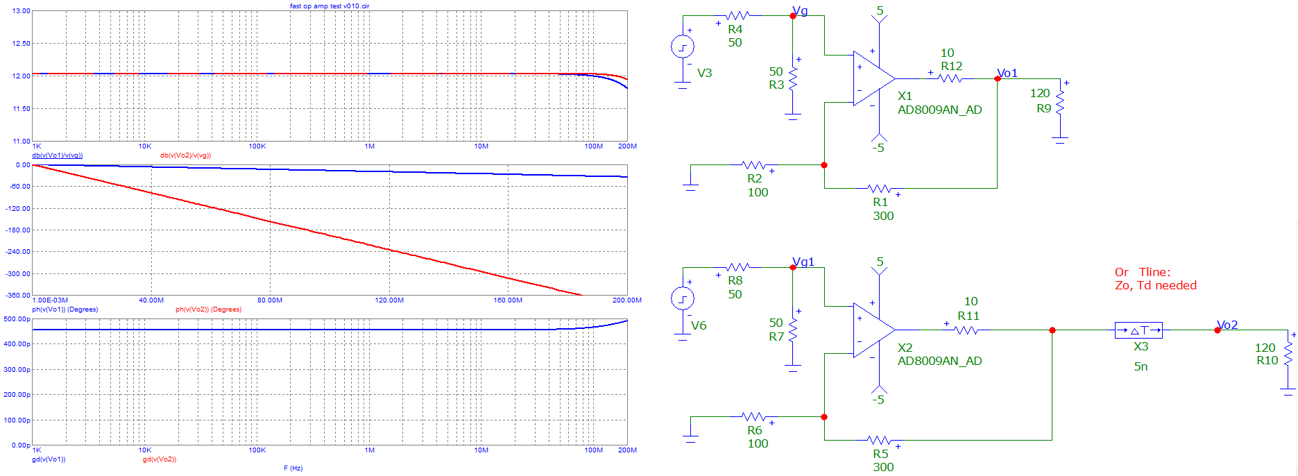
Datasheet frequency response:
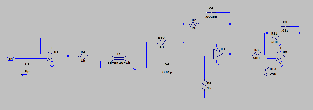
LTspice Model attempt
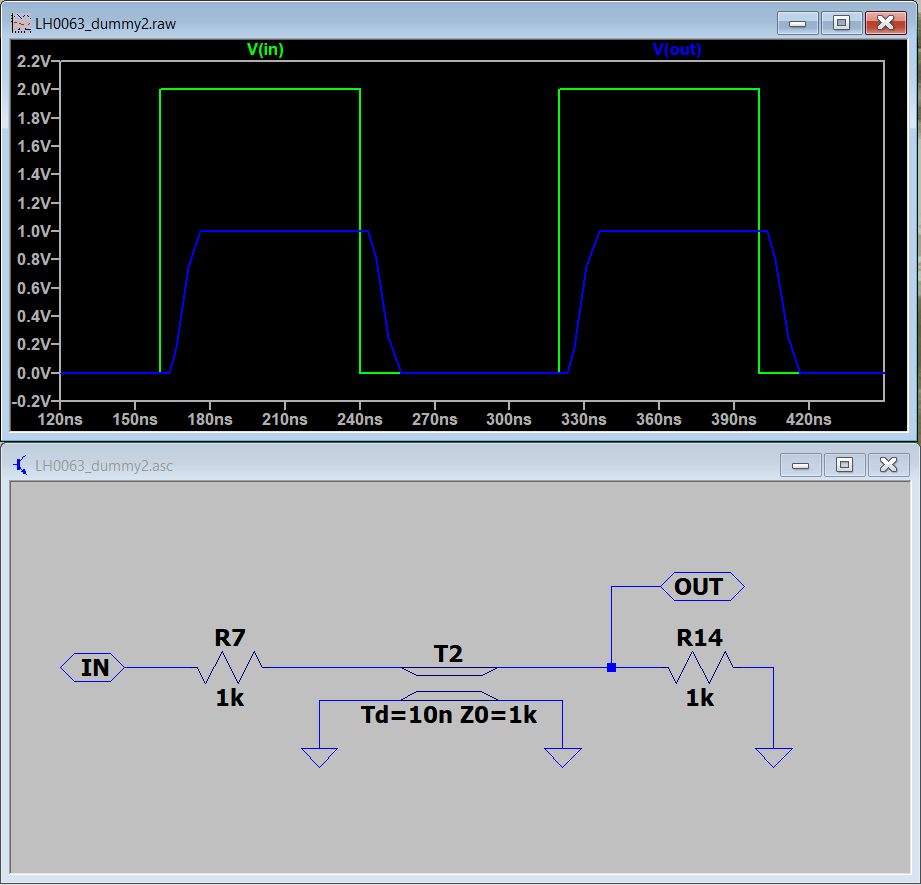
I tried to introduce the prop-delay using a transmission line (tline). The problem is tline also limits the edge rate, rather than just causing a delay:
Here is the simple versions I made (don't care about Bandwidth):
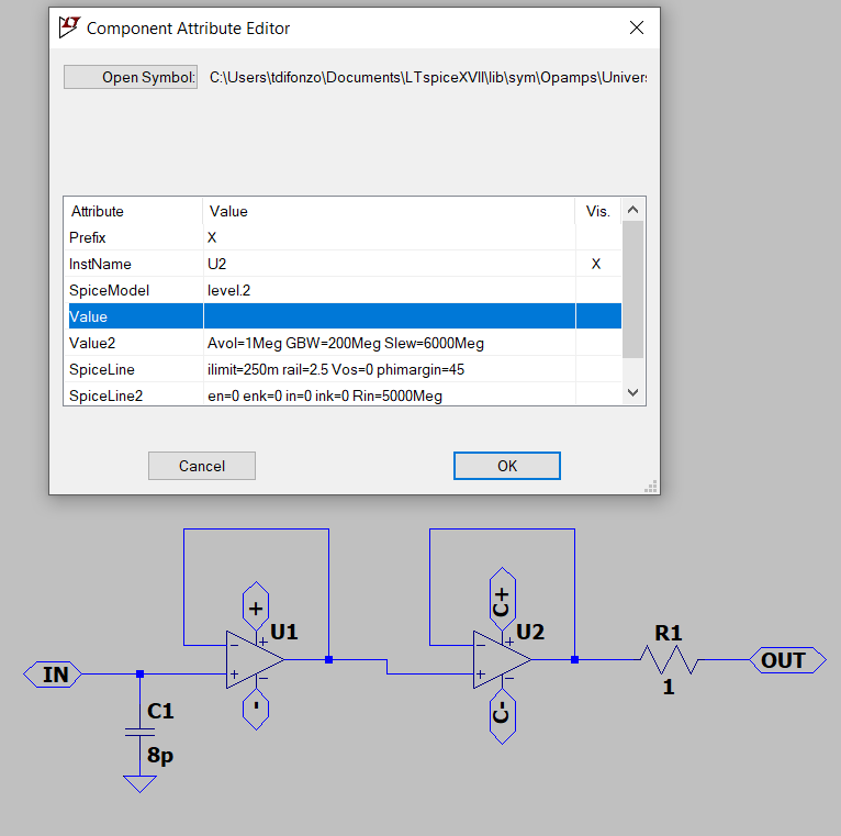
This I my attempt using tline to introduce the delay, mediocre results.

.transtatement to something like1p. You can also try thedelayorabsdelayfunctions with a B-source, but I think you'll have the same problem. See the "B. Arbitrary Behavioral Voltage or Current Sources" section of the LTspice help for syntax of those functions. \$\endgroup\$level.3bwith appropriate settings and you should get a built-in analog delay, which may be better than thetlinedue to the continuous nature of the tie response. Here's a quick test. \$\endgroup\$tripdvandtripdtparameters of a B-source to do this. You can actually still use the tline for your signal path (if you prefer; you still haven't explained why) and throw the B-source off to the side, since its sole purpose would be to force the timesteps for the rest of the circuit. \$\endgroup\$