0
\$\begingroup\$

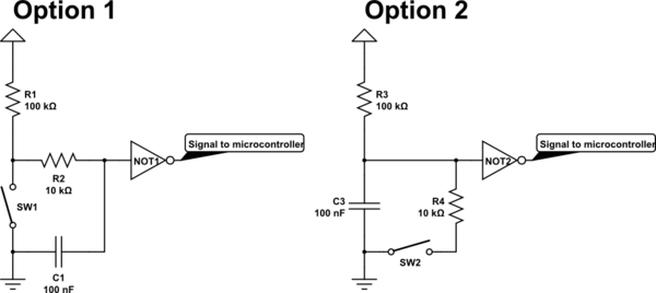
I'm trying to figure out the way of debouncing encoders and tact buttons with Schmidt triggers, but I'm confused with 2 existing schematics:

schematic

simulate this circuit – Schematic created using CircuitLab

Which of those two options are right? Values are shown for 5.0V inputs level, would the be the same for 3.3V? Or for 3.3V I should use another Schmidt trigger IC (not 7414)?

Thanks in advance!

\$\endgroup\$
5
  • 1
    \$\begingroup\$ Encoders should not need debouncing. Tact switches are often debounced in firmware. Are you sure you need to add a logic gate for debounce? \$\endgroup\$
    – user57037
    Commented Jul 10, 2017 at 5:05
  • \$\begingroup\$ @mkeith that "gate" is just for illustrating the presence of Schmidt trigger ( I didn't find the proper symbol in CircuitLab service). \$\endgroup\$ Commented Jul 10, 2017 at 5:14
  • \$\begingroup\$ @mkeith Yeah, some encoders need debouncing. This one, for example, when turned fast: sparkfun.com/datasheets/Components/TW-700198.pdf \$\endgroup\$
    – jonk
    Commented Jul 10, 2017 at 5:22
  • \$\begingroup\$ Option 1. (Don't use option 2.) You can always use the "very boutique" MC14490 part. Gives you 6 fancy debouncers in one IC package. PRICEY! \$\endgroup\$
    – jonk
    Commented Jul 10, 2017 at 6:01
  • \$\begingroup\$ I include the Schmidt trigger as a type of logic gate. I still suggest you debounce your button in firmware. That is the normal way to do it. I can't even remember the last time I saw external debounce hardware on a button connected to a micro-controller in a mass-produced product. \$\endgroup\$
    – user57037
    Commented Jul 10, 2017 at 8:09

1 Answer 1

1
\$\begingroup\$

The first is the better option. Notice that the second circuit does not provide the output gate with the intended 0 V ground when the switch is closed. It is supplied a low level voltage through a voltage divider.

However, when the switch is closed in the first circuit, the gate's input is pulled down to ground, but slowly- as the cap discharges. This is what you want.

Edit also read all the comments. I agree with mkeith that, if this is for a microcontroller project, consider denouncing in firmware.

And jonk is right (as he often is) that there may be better, prepackaged, options depending on your needs.

Edit: 3.3 V will work fine with a 7414, provided you supply the IC with 5 V nominal on the VCC pin to power the chip. The resistors are up to you. The values of the resistors and capacitor affects the capacitor's charge/discharge time. Higher values provide more denouncing, but increase the wait time allowed between subsequent triggers. You might also want to add a voltage follower as an output stage.

For Example: Example circuit
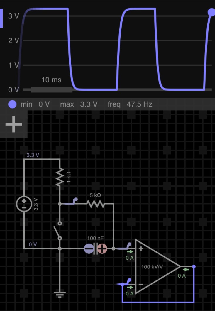
and...

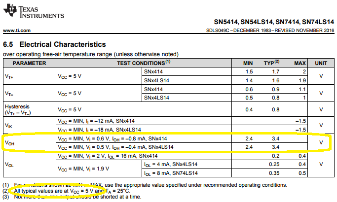
Regarding your 7414 question in the comments: 7414 Datasheet
\$\endgroup\$
5
  • \$\begingroup\$ Thanks for answer. But what about resistor values? Would the be the same for 3.3V signal level input? Or for 3.3V the 7414 will not work? \$\endgroup\$ Commented Jul 11, 2017 at 18:03
  • \$\begingroup\$ See addition to the answer \$\endgroup\$ Commented Jul 11, 2017 at 19:06
  • \$\begingroup\$ Well. Now it confuses me even more. If I understand the 7414 datasheet properly, it can give the output signal 0 or Vcc. If I'll do as you've described: "7414, provided you supply the IC with 5 V nominal on the VCC pin to power the chip", the 7414 output will be still 5.0V level (even if it will understand the 3.3V input as logic 1). What I wanted - attaching the output to STM32F103****, that has 3.3V signal level. Maybe, the proper question(s) is: "Will this circuit run with 3.3V input level? Could it use the 3.3V as supply? Could it produce the 3.3V level output?" \$\endgroup\$ Commented Jul 11, 2017 at 19:49
  • \$\begingroup\$ No, from the datasheet it looks like the supply voltage is 5 V nominal, and V_OH is 3.3 V. \$\endgroup\$ Commented Jul 11, 2017 at 20:08
  • \$\begingroup\$ see edit. We're getting off topic though. I would advise you click Accept Answer, and post a new question if you need advice on using the chip. \$\endgroup\$ Commented Jul 11, 2017 at 20:17

Your Answer

By clicking “Post Your Answer”, you agree to our terms of service and acknowledge you have read our privacy policy.

Not the answer you're looking for? Browse other questions tagged or ask your own question.