0
\$\begingroup\$

I must design a 4-bit shift register circuit. I am pretty sure that I need 4 D flip-flops sharing the same clock. right??

So I did that and here is the result: wat
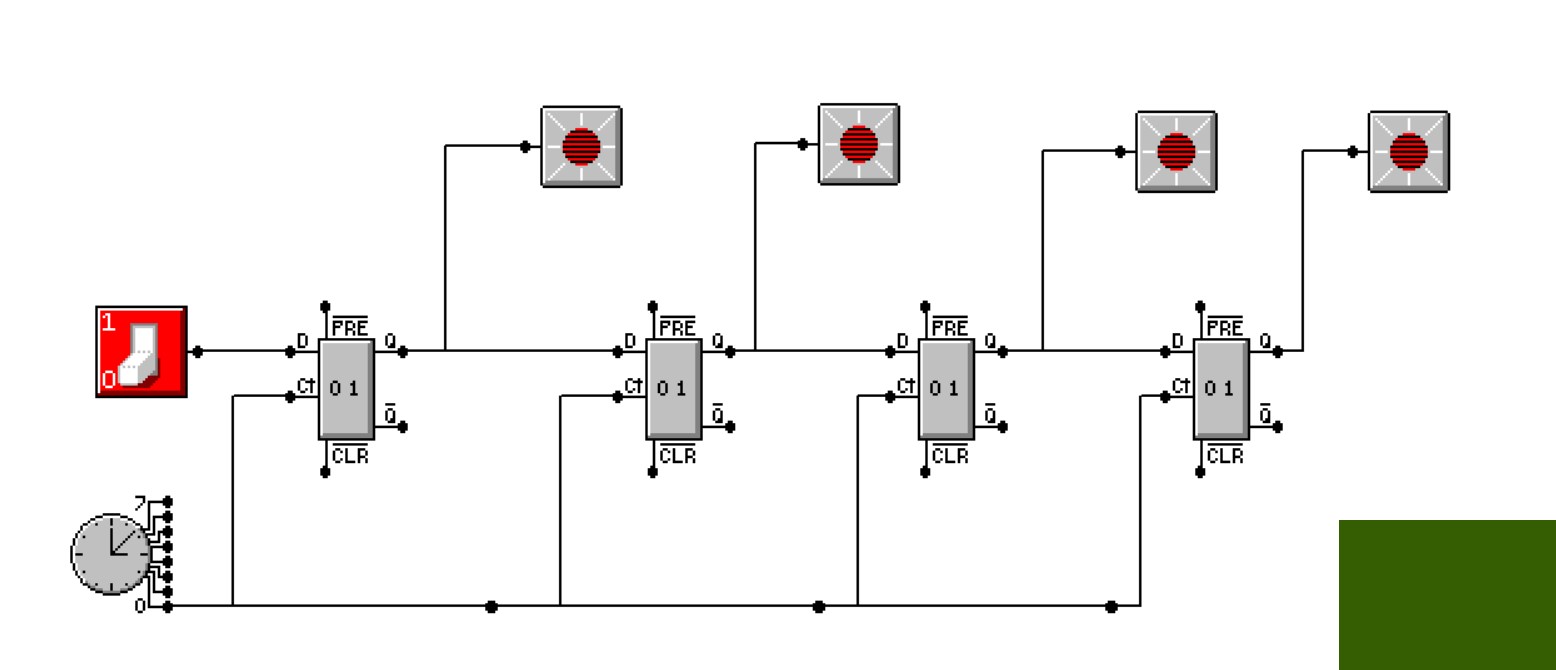
As you the LED lights are neither completely off (0) nor completely on (1) rather they seem to be in this, uh, indifferent state? Anyway, the point is, it is not working no matter where i put the switch.

If I go to each ff and remove the preset/clear lines the circuit works! but I do not understand why that is an issue? Why doesn't it just work the way I drew it?

\$\endgroup\$
6
  • 1
    \$\begingroup\$ What happens if you tie the preset and clear lines high? \$\endgroup\$ Commented Apr 21, 2020 at 13:38
  • \$\begingroup\$ That's what Lois would say. \$\endgroup\$
    – Andy aka
    Commented Apr 21, 2020 at 13:46
  • \$\begingroup\$ Hi! Welcome here. Please edit your question: the title should describe your problem in someway; Mabye something like "4-bit shift register: unknown state". Also, this really has nothing to do with multimedia, does it? \$\endgroup\$ Commented Apr 21, 2020 at 13:58
  • \$\begingroup\$ @PeterSmith i did that and it seems to work that way.. but like, w h y \$\endgroup\$ Commented Apr 21, 2020 at 14:10
  • \$\begingroup\$ @petergriffin; I am not familiar with your tool but very probably because the inputs were floating and needed to be pulled to a valid state (in this case high to allow the register to operate). \$\endgroup\$ Commented Apr 21, 2020 at 14:15

2 Answers 2

1
\$\begingroup\$

In a logic circuit, you typically cannot leave any pins floating (not connected to anything).

If you include preset and clear control lines, they need to be set to a logic level, either high (your logic-level voltage) or low (circuit ground). If they are left floating, then the flip flops are in an undefined state. When you remove the preset and clear lines from your simulation, then the flip-flops will operate normally because it doesn't expect any input from them. D flip-flops can come with or without these additional control lines.

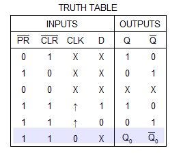
Take a look at the truth table for D flip flop with preset and clear control lines.

D flip-flop truth table

The preset and clear lines are considered "active low" which means they perform their functions when pulled low. When they are pulled high, the clock and D control the outputs as you would expect. Notice, if they are both pulled low, the outputs are in an undefined state (represented by 'X').

  • Preset - sets the output (Q) high
  • Clear - clears the output (sets Q low)
\$\endgroup\$
0
\$\begingroup\$

You could get away with leaving pins open in early bipolar IC families. It was always considered bad practice. Things could go wrong, but rarely did. Even so the only excuse for doing so was to save the expense of a resistor. It was another bad practice to tie input pins directly to Vcc. A resistor to Vcc provided protection from transients on the power bus. The maximum voltage rating for Vcc is higher than that for inputs. (The 74LS family was the first one that allowed direct connection for pulling up unused pins, because its inputs were diodes rather than emitters.)

It has never been allowable to leave CMOS inputs open. Unlike bipolar logic, an open input is not seen as a logic one. In some cases it's seen as an intermediate state, P-channel and N-channel MOS transistors are simultaneously ON, and the increased power can damage the IC.

All of that is TLDR, but your simulator has good reason to disallow open input pins. If it allowed specifying the flip-flops by part number, it would probably show the shift register working for 7474, but not for 74HC74.

\$\endgroup\$

Your Answer

By clicking “Post Your Answer”, you agree to our terms of service and acknowledge you have read our privacy policy.

Not the answer you're looking for? Browse other questions tagged or ask your own question.