1
\$\begingroup\$

The following circuit diagram what are A' and B'?
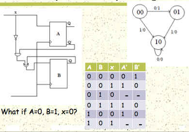
Circuit, truth table, and Finite State Machine

The question in the slide asks what happens if A=0, B=1, and x=0.
I understand what it means when x=0, but what exactly does this mean when A=0 and B=1? The way A and B are labeled in the diagram it appears like they represent the hardware device, not an input. Can someone explain to me what A and B are exactly?

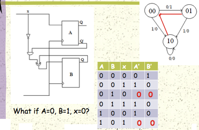
In the following diagram we are given the answer if A=0,B=1,and x=0 in red. Can somebody explain how they arrived at this answer?

Trying to make sense if it myself, here is my train of thought:

Input x is fed into a NOT gate, making it x'. x' is fed into an AND gate with Q', thus making the output (x'^Q'). Which is then fed into an OR gate with Q, giving you Q OR (x' ^ Q') = (Q OR x') AND (Q OR Q') = Q OR x'. This is fed into both inputs of B, which doesn't make any sense to me. At this point I am lost, so I would appreciate some guidance what happens to Q OR x'?
enter image description here

\$\endgroup\$

1 Answer 1

4
\$\begingroup\$

A and B are D latches; on the clock edge, the value on the input is latched to the Q output.

A = 1 means that the Q output associated with the A latch is high (the complementary output is thus low).

A = 0 means that the Q output associated with the A latch is low (the complementary output is thus high).

A' is the value of A after the next clock edge.

This is a state machine. A and B represent the current state. The current state, along with the input x, determine the next state denoted by the primes on A and B.

So, for example, the input to the A latch is x so, if x = 0, on the next clock edge, 0 will be latched, i.e., the Q output of the A latch will be low; A' = 0.

Following the logic, the input to the B latch is: \$(\bar x \cdot \bar A) + B \$

So, for x=0, A = 0, B = 0, the input to B is 1 and thus, after the next clock edge the Q output of B will be high; B' = 1.

UPDATE: a closer look shows that the schematic does not match the state transition table. It's obvious that the input to the A latch is x and so, A' = x according to the schematic. However, the 5th row in the state transition table has A' = 1 when x = 0. That's not consistent.

\$\endgroup\$
5
  • \$\begingroup\$ Hi Alfred - I understood everything you said except for the part "input to the B latch is: \$(\bar x \cdot \bar A) + B \$. Can you explain to me why you are using As and Bs instead of Q and Q' ? For example, where you wrote $\bar A$\ I expected it to be\$ bar Q $\. Where you wrote \$B\$ I expected it to be \$Q$\. If you could please explain to me how you exchanged the Q and Q' with A' and B I would really appreciate it. \$\endgroup\$ Commented Nov 26, 2012 at 0:10
  • \$\begingroup\$ A is the (current) Q output of the A latch. B is the (current) Q output of the B latch. Sorry if I didn't quite make that clear. If it's not quite yet clear, pencil in an "A" over the Q output of the A latch and a "B" over the Q output of the B latch (and likewise for the complements) and then write the logic equations. \$\endgroup\$ Commented Nov 26, 2012 at 0:12
  • \$\begingroup\$ So when A=0,B=1,x=0, using your logic, I get (0' * 0') + 1 = (1 * 1) + 1 = 1. But the answer for B' = 0. Why is this? \$\endgroup\$ Commented Nov 26, 2012 at 1:12
  • \$\begingroup\$ When B=1 this means the Q output for latch B is high, does this negate your formula? I guess I'm confused what the purpose of knowing whether Q for either latch is high or low. \$\endgroup\$ Commented Nov 26, 2012 at 1:15
  • \$\begingroup\$ @user1068636, I've updated my answer to address the inconsistency between the schematic and transition table. \$\endgroup\$ Commented Nov 26, 2012 at 1:52

Your Answer

By clicking “Post Your Answer”, you agree to our terms of service and acknowledge you have read our privacy policy.

Not the answer you're looking for? Browse other questions tagged or ask your own question.