2
\$\begingroup\$

So from what I understand transistors are one of the most important electronic elements for computers because of TTL (Transistors-Transistors Logic).

Is this true? If so, how exactly does this work? I have heard the terms "logic gate" and "logic block" tossed around.

\$\endgroup\$
2
  • 4
    \$\begingroup\$ TTL hasn't really been in common use since the 1980s. \$\endgroup\$ Commented Jul 2, 2014 at 12:02
  • \$\begingroup\$ While the acronym "TTL" came into widespread use with the advent of TI's SN7400 and SN5400 Transistor-Transistor-Logic families, its meaning as a descriptor for a particular set of logic threshold levels has been in use now for a very long time and is hardly moribund, as attested to by the plethora of "TTL compatible" stuff around. Not only that, checking DigiKey's stock levels of bipolar 74XX and it becomes apparent that while there may not be an awful lot of new design being done with bipolar TTL, there's an awful lot of it out there still in common use. \$\endgroup\$
    – EM Fields
    Commented Jul 2, 2014 at 12:56

4 Answers 4

8
\$\begingroup\$

Trying to define what is the "most important" element of a circuit is pointless.

As for what a logic gate is, it's a circuit that operates on signals with discrete states. Overwhelmingly, this is done using two states only, high and low. There are good electrical reasons for why two states is much easier to deal with and operate on than multiple states in a single signal. There is more detail on that here.

Therefore, in practise, "logic gate" refers to something that manipulates binary signals. Since the two states can be thought of as representing true and false, the world of Boolean logic theory can be applied to these systems. The simplest logic gate of all is the inverter, which performs the boolean NOT function. The next more complicated are the 2-input 1-output logic gates. These have function like AND, NAND, OR, NOR, and XOR.

In theory (going back to boolean logic), you can build up any more complex function from only NAND or NOR gates, although making those complex function more explicitly from a bunch of transistors is often more efficient.

From the basic building blocks above, it is possible to construct flip-flop, counters, adders, etc, etc, etc. A whole processor will contain many of these things, which all eventually decompose down to transistors. Nowadays we have high level logic design tools so that humans specify the high level logic to perform, and the tools automatically generate the sea of transistors required to realize it.

\$\endgroup\$
3
  • 2
    \$\begingroup\$ Maybe I'm being picky here, but tools do not "automatically generate the sea of transistors required to realize it". In modern digital design flows the basic unit is the standard-cell which is a Logic Gate, Flip-Flop etc.. The Standard-Cell is composed of transistors appropriately connected. Typically the standard cells are automatically wired together to form the overall function. In an FPGA the standard cells are configurable logic blocks (CLBs) \$\endgroup\$
    – akellyirl
    Commented Jul 2, 2014 at 13:37
  • \$\begingroup\$ @akelly: Which all ultimately boil down to a bunch of transistor appropriately connected. Yes, in some technologies transistors are already in fixed places partially pre-wired. \$\endgroup\$ Commented Jul 2, 2014 at 16:44
  • \$\begingroup\$ electronics.stackexchange.com/q/471276/235138 please explain this question, iam the asker \$\endgroup\$
    – user42757
    Commented Dec 12, 2019 at 3:34
2
\$\begingroup\$

Transistors are the foundation blocks of computers and embedded systems. TTL is used to refer usually to an electronic circuit that uses transistors for both the logic function (whether to be on or off) and the amplifying function (usable currents and voltages), or more colloquially to binary voltage levels of 0V-5V (because this range is what TTL dedicated chips use, as well as many other electronic devices).

A logic gate is an arrangement of transistors that decide an output based on the values of the inputs. Typical logic gates include AND, OR, NOT, NAND, NOR, XOR.

Example of a logic gate:

AND

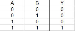
Basic definition: when all inputs are high (5V), the output will be high (5V), otherwise the output will be low (0V).

Therefore: when Input A and Input B are LOW, Output Y will be low. When Input A is LOW and Input B is HIGH, Output Y will be low. When Input A is HIGH and Input B is LOW, Output Y will be LOW. When Input A is HIGH and Input B is HIGH, Output Y will be HIGH.enter image description here

\$\endgroup\$
2
\$\begingroup\$

Logic "'gates" are called that because they open and allow something to pass through only when they're opened according to certain rules.

For instance, consider a bull in a pen with a gate which will open - and let the bull out - only if two people open the gate together. That's called an AND gate because it'll only open if person "A" AND person "B" open the gate together.

On the other hand, if either of two people could open the gate it would be called an OR gate since person "A" OR person "B" (or both) could open it.

\$\endgroup\$
1
\$\begingroup\$

The idea of Boolean functions is old and George Boole wrote his famous "Mathematical Analysis of Logic" before 1900. It wasn't until Claude Shannon wrote his Masters degree Thesis, "A Symbolic Analysis of Relay and Switching Circuits" in 1938 that the connection between logical functions and implementation using switching devices was made.

A logic gate is a device that implements a Boolean function ( = logical function) such as AND, OR, NAND, XOR and others... The definition is broad and hints you could implement logic gates (functions) in many ways. You could go extreme and implement functions using mechanical switches or even balls and levers (I've seen it done!).

TTL is one of the implementation methods for logic functions. It uses BJT transistors and resistors as construction elements. TTL got huge early on and set standards to other implementations that followed in later years.

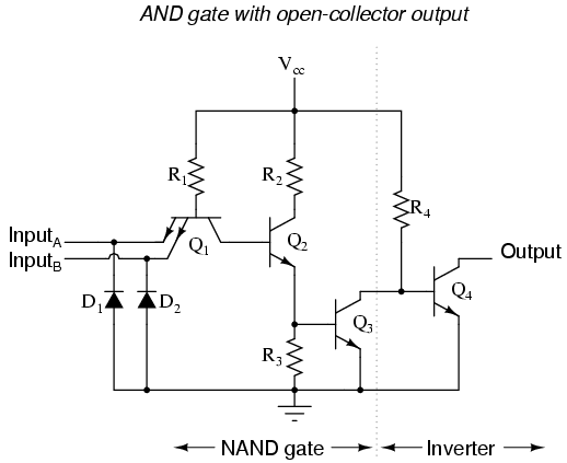
An example of the logic function AND implemented in TTL: enter image description here Please note that output of this implementation is open collector so you would wire the output to VCC via a resistor. If you analyze the circuit you will see that the relations between inputs and output are expressed by the truth table of the AND function. I like this circuit because you can see how a NAND function is implemented and how a NOT function is implemented as well (like having 3 in 1). The transistors are of course working either in cut-off or saturation so the output is either high voltage or low voltage which corresponds to the 1 and 0 states in Boolean algebra.

\$\endgroup\$

Your Answer

By clicking “Post Your Answer”, you agree to our terms of service and acknowledge you have read our privacy policy.

Not the answer you're looking for? Browse other questions tagged or ask your own question.