0
\$\begingroup\$

I'm reading J. Clark Scott's book But How Do It Know.

When he is describing registers and the bus he illustrates this at one point as five registers sequentially parallel-connected to a bus.

As you turn on the enabler of one register all other registers will copy its byte if their signal is turned on.

If R3s enabler is on it sends signals both left and right, to R2 and R4, and all other registers.

My assumption: The bus is a loop connected to ground at the end so the current from R3 that is sent on the bus has parallel paths to ground, left and right.

My question: Is the bus connected to ground in both directions, and how is the current maintained on the bus when it is being split into the each registers' inputs?

\$\endgroup\$
8
  • \$\begingroup\$ Please clarify your specific problem or provide additional details to highlight exactly what you need. As it's currently written, it's hard to tell exactly what you're asking. \$\endgroup\$
    – Community Bot
    Commented Oct 28, 2021 at 8:12
  • \$\begingroup\$ This is incredibly vague and fuzzy. I don't see how anyone can explain in which way currents flow in some abstract artificial system. Also, "bus" could pretty much mean everything. \$\endgroup\$
    – Lundin
    Commented Oct 28, 2021 at 8:23
  • \$\begingroup\$ As one of my professors pointed out, unless you define it otherwise a bus is a big red thing with four wheels. \$\endgroup\$
    – Frog
    Commented Oct 28, 2021 at 8:34
  • \$\begingroup\$ Sorry, I'm dipping my toe in to this world for the first time and my inexperience might show. But hopefully I will learn from this and be clearer in the future. But the feedback is welcomed, feels like I have a bunch of teachers. \$\endgroup\$ Commented Oct 28, 2021 at 8:38
  • \$\begingroup\$ "My assumption: The bus is a loop connected to ground at the end ..." - no, a bus is not typically connected to ground anywhere. In simplistic terms, you're interested in voltage levels on the bus, not current flow. Any current flowing is just an inconvenient side-effect. \$\endgroup\$
    – brhans
    Commented Oct 28, 2021 at 11:44

1 Answer 1

1
\$\begingroup\$
  • Instead of thinking of currents think of voltages.

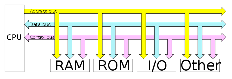
enter image description here

Figure 1. Computer architecture showing address, data and control busses. Source: Wikispaces.

  • Remember that "bus" is short for "omnibus" (Latin) which means "for all".
  • If any device applies a voltage onto the bus then all others connected to the bus can see it and read it.

... how is the current maintained when it is being split into the the other registers' inputs?

Each logic device will have a rated output "fan-out" which tells you how many inputs can be fed from that output. This used to be a big issue with TTL logic which had high input currents but isn't generally an issue on CMOS as the input resistance is so high that negligible current is drawn (other than to charge up the input capacitance). You can generally consider the inputs as voltage driven.

It might be worth noting that each device on the bus will load the bus whether enabled or not because the enable/disable feature will be implemented after the input buffer (which is what creates the bus load).

See my answer to What is a bus (physically) in digital design? which has more on the topic.

\$\endgroup\$
1
  • \$\begingroup\$ Thank you. I realise that I'm just starting to learn to basics and some of these questions will be answered as I keep reading, but it's a great help to be able to get answers to the head scratchers I happen upon so. \$\endgroup\$ Commented Oct 28, 2021 at 8:28

Not the answer you're looking for? Browse other questions tagged or ask your own question.