2
\$\begingroup\$

I have 31 digital inputs (each is high or low) and want one digital output which is high only if at least 16 inputs are high. How can I implement this "majority" function (which is also the most significant bit of the sum) with the fewest MOS transistors?

As a bonus, I'd also like to know the fastest-in-worst-case implementation.

\$\endgroup\$
4
  • 4
    \$\begingroup\$ Hmm, the smell of homework tickles my nostrils. Questions about your homework is OK as long as you show us what you've researched / considered sofar and have a specific question about that. You seem to have done nothing to help yourself so we're not going to help you either. \$\endgroup\$ Commented Mar 18, 2016 at 22:54
  • 1
    \$\begingroup\$ It's not homework. I have long since graduated. It's a simply-stated but hard-to-solve problem, my favorite type, for which the two answers so far had occurred to me. I was simply hoping someone had another trick for solving this. \$\endgroup\$
    – bobuhito
    Commented Mar 19, 2016 at 6:09
  • 1
    \$\begingroup\$ Homework or not (and I have had homework also after getting my Master's when following a course, a proper course, the one where you get homework ;-) ) the most important point is that you showed no efforts to get to a solution yourself. \$\endgroup\$ Commented Mar 19, 2016 at 15:50
  • \$\begingroup\$ The analog version of the "winner take all" circuit is only 31*2 +4 FETs. You take digital inputs and get a digital output, but the intermediate state is current. Something to file back in the archives for an alternative solution. \$\endgroup\$
    – b degnan
    Commented Mar 20, 2016 at 15:47

4 Answers 4

2
\$\begingroup\$

Configure 31 MOS transistors as switchable current sources which feed a 32nd which is configured as a current sink at 15 times the source currents. Then observe the voltage of the summing node.

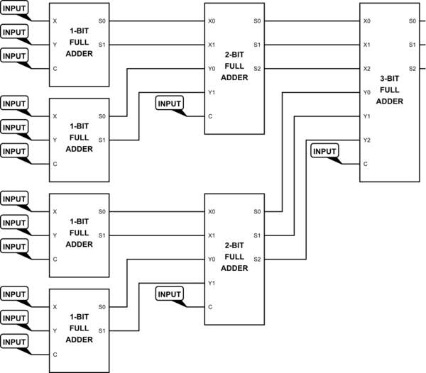
EDIT - I should not play games. The title said "Digital", so it's digital we'll go. One configuration would be

schematic

simulate this circuit – Schematic created using CircuitLab

This handles 15 inputs. Duplicate it and add a 4-bit full adder and Bob's your uncle. I haven't shown the last adder, but you should be able to figure it out for yourself.

And, of course, if you build this with BJTs, as with TTL or ECL logic, there will be no MOS transistors used at all.

\$\endgroup\$
5
  • \$\begingroup\$ Better make the sink 15.5x the source current. \$\endgroup\$
    – Dave Tweed
    Commented Mar 18, 2016 at 23:08
  • 3
    \$\begingroup\$ Since the design metric is "fewest MOS transistors", it would be better to do this with BJTs and relays. \$\endgroup\$
    – The Photon
    Commented Mar 18, 2016 at 23:28
  • \$\begingroup\$ For the record, I would probably build this with your 32 transistors plus five series inverter for the final gain stage. So, the total is 42 transistors. This solution is sensitive to analog MOS characteristics, so I was hoping there was a digital trick instead...let me see if other answers come in. \$\endgroup\$
    – bobuhito
    Commented Mar 19, 2016 at 6:18
  • \$\begingroup\$ @bobuhito - Since D/A converters are made with much higher precision (a 12-bit needs switch accuracy in the range of .025% vs the 3 % needed here), and a monolithic solution will cause matching temperature effects, I wouldn't expect a problem. But it's true that I'm playing games. A digital solution would involve 8 1-bit full adders, 4 2-bit full adders, 2 3-bit full adders, and 1 4-bit full adder. You can figure the transistor count from that. \$\endgroup\$ Commented Mar 19, 2016 at 13:51
  • \$\begingroup\$ Your digital solution has at least 200 transistors (using high-power adders to minimize transistor count), so I prefer the original analog answer better...but still hoping to see a trick and might give someone a free "clocking signal" to help. As for @ThePhoton suggesting BJTs/relays, of course they are not allowed; he may as well have suggested using one human being to connect a wire manually depending upon how many inputs cause a shock! \$\endgroup\$
    – bobuhito
    Commented Mar 20, 2016 at 20:27
1
\$\begingroup\$

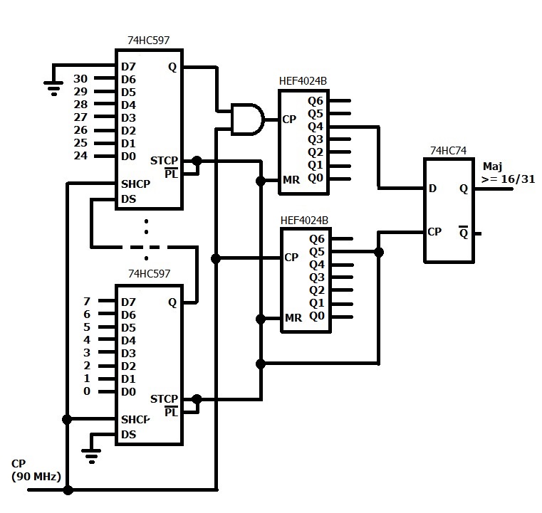
Connect the 31 inputs (0-30 in the diagram below) to four 8-bit parallel-in, serial out shift registers such as the 74HC597 which are cascaded in series (only two shown). Clock the serial output of the last register into a binary counter such as the 74HC4024. Use another 74HC4024 counter to keep track of when 32 clock pulses have occurred which then repeats the cycle.
enter image description here

For some crazy reason the original CD4024, and the follow-on 74HC4024 started numbering their flip-flops with Q1 instead of Q0. Very confusing. So I am showing the NXP part (HEF4024B) instead which corrected this anomaly.

So every 32 clock pulses (when Q5 of the second counter goes high), if at least 16 inputs were high (meaning Q4 of the first counter is 1), then this status is latched into a D-type flip-flop (74HC74) and remembered until the next set of 32 clock pulses complete. Meanwhile the inputs are reloaded in parallel to the shift registers.

This is somewhat of a special case, in that the majority threshold is a power of two, so only one pin (in this case Q4, representing 16-31) has to be queried. If instead the threshold was 14/27 for example, an address decoder would need to be added, to separate out the values 14 and 15 in addition to 16.

With a 90 MHz input clock, there will be a maximum of 355 ns delay from a change in the input until the update of majority status at the output.

Note -- not all "glue logic" necessarily shown, but this should get across the idea.

\$\endgroup\$
1
  • \$\begingroup\$ I'd like to see a transistor-level schematic to count, but figure this is more than 200 transistors if standard JK flip-flops are used. This approach is good if only there were a slick way to serialize and count a bunch of inputs. \$\endgroup\$
    – bobuhito
    Commented Mar 20, 2016 at 20:35
0
\$\begingroup\$

It seems like you are confusing a few concepts here. You are saying you want a majority voter circuit. In which case you could make a very large truth table and reduce the circuit using reduction techniques. For example:

Input / Output

000 / 0

001 / 0

010 / 0

011 / 1

100 / 0

101 / 1

...so on and so forth. Then when you have the final logic gates, simply disassemble the gate into your transistor count. You are not going to be able to do this for 32 bits unless you have a lot of time on your hands. Assuming it took you 1 second to do each combination it will still take you 2^32 seconds, or 136 years. Having lived this long you would then have to do some type of gate reduction.

When you say "The most significant bit of the sum" this is a little confusing. Consider you have 3 inputs that are high, the most significant bit of the sum is 1, likewise with 2. If your majority counter had only 3 bits, this information wouldn't tell you anything.

"The fastest in-worst-case implementation" sounds like the sum of the gate delays that would happen in the worst case realization; the most cascaded realization would have the largest delay.

Hint: Latches and Flip flops are also made out of logic gates, which are also made out of transistors. Maybe you could make a shift register and a counter, then use a little combinational logic on the output of the counter.

Good luck.

\$\endgroup\$
5
  • 2
    \$\begingroup\$ Since the circuit is intended to handle 31 circuits, a complete sum of the inputs will be a 5-bit number. If, as in your example, there were to be only 3 inputs, the sum would be a 2-bit number, and the msb would, in fact, indicate that 2 or more inputs (a majority) were 1. \$\endgroup\$ Commented Mar 18, 2016 at 23:44
  • \$\begingroup\$ The sum of a 31 bit number is a 5 bit number? That doesn't make any sense. Also, the sum of all the bits in 00101 is 00100 + 00001, which is 00101... The MSB is 00100; how would you tell the difference between 00101 and 00111 just by looking at the most significant bit? \$\endgroup\$ Commented Mar 19, 2016 at 20:12
  • \$\begingroup\$ No, but 31 is expressible as a 5 bit number, 0b11111. The sum of all the bits in the bit field 00101 is 2 (two bits are high), which is 10. The rest of your question doesn't make much sense. \$\endgroup\$ Commented Mar 19, 2016 at 20:30
  • \$\begingroup\$ You lost me. I thought what he meant by "31 digital inputs" that can each be high or low, so I was thinking these are individual bits in a word; and the object was to determine if a majority of these bits were high. \$\endgroup\$ Commented Mar 19, 2016 at 21:02
  • \$\begingroup\$ It doesn't matter if a bit is msb or lsb. If it's high, it's high. If the 16 msbs are high, the majority of the 31 bits are high. If the 16 lsbs are high, the majority of the 31 bits are high. Their value doesn't matter. Why do you think they do? The question does not even remotely apply to the value of the bits. It just asks if a majority of them are high or not. \$\endgroup\$ Commented Mar 19, 2016 at 21:25
-1
\$\begingroup\$

I'm mostly an analog person, so I would do this using analog techniques.

Sum all of the inputs together in a summing amplifier. Feed the output of the amplifier to a comparitor that trips when the desired number of inputs is HI.

This can be simplified to a resistive summer (no op-amp needed) and a comparitor.

\$\endgroup\$
1
  • 1
    \$\begingroup\$ OP's question title is "Digital Circuit to Check for Majority". (I didn't downvote you though!) \$\endgroup\$
    – Transistor
    Commented Mar 20, 2016 at 19:36

Your Answer

By clicking “Post Your Answer”, you agree to our terms of service and acknowledge you have read our privacy policy.

Not the answer you're looking for? Browse other questions tagged or ask your own question.