0
\$\begingroup\$

I'm trying to implement a autocorrelation module into my FPGA. I have been doing some research on the internet and there are some complicated and advanced methods that use a Fast Fourier Transform (FFT) to do the autocorrelation.

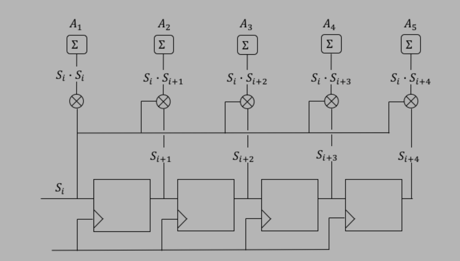
However, all I need is a simple implementation, nothing too fancy. I came across this digital logic site that has this diagram:

Design from autocorrelation website

Essentially, what I got out of this was that we chain D-flip-flops (DFF) to create a shift register. From there we pull from the shift register or different DFFs and run them into a multiplier with the original Si, then add the output. So my implementation from a program called digital is this:

Implementation using Digital application

Which I believe is the same, however, I am noticing some variations. I added more DFFs because I want to be able to correlate more bits. I also am not really sure if I implemented the "Sums" correctly; I also skipped the fist add from the first multiply for this reason.

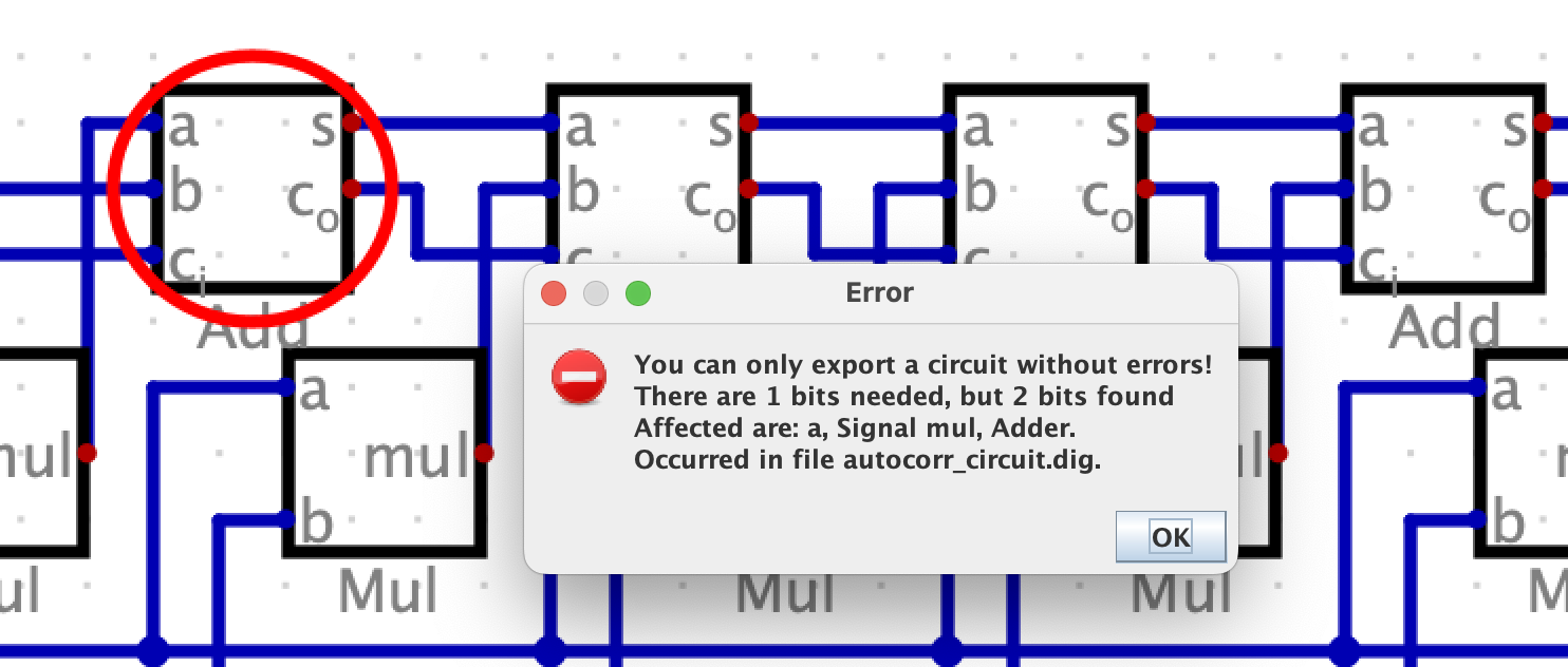
Some other issues I had include issues from the program. I ultimately used this program because I can take the design and get Verilog code out of it. But when I try to export as Verilog I get the error:

Verilog import error

Can anyone help confirm if I'm on the right track with this implementation or if it is correct? It seems like the first adder is having issues but I am also unsure of what the first Ci would be. In Verilog I could just set it to a 0 bit, but I am not sure how to do that in a design.

\$\endgroup\$

1 Answer 1

1
\$\begingroup\$

The block diagram implementation is incorrect.

Firstly, let me quickly clarify what autocorrelation is, with reference to the example you have shared. It should help you to draw the diagram correctly. (Note: The standard time indexing notation for eg. in Wikipedia is different from what is used here)

I'll assume that I have \$N\$ readings sent into the system in the order \$S_N, S_{N-1}, \dots S_1, S_0\$. The autocorrelation of this discrete-time signal \$S_n\$ at a time lag \$k\$ is

$$R_{ss}(k)=\sum_{k=0}^{N}S_i\cdot S_{i+k}$$

For a 5-stage autocorrelation as given in your example, there are 5 outputs.

The autocorrelation at lag \$k=0,1,\dots 4\$ is $$ R_{ss}(0) = A_1 = \sum_{k=0}^{N}S_i\cdot S_{i}$$ $$ R_{ss}(1) = A_2 = \sum_{k=0}^{N}S_i\cdot S_{i+1}$$ $$\dots$$ $$ R_{ss}(4) = A_5 = \sum_{k=0}^{N}S_i\cdot S_{i+4}$$

The product terms at each stage are accumulated separately (and not summed up across each stage) to generate the correlation at that particular stage.

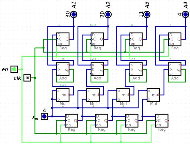
I created this up in digital and the connections are shown below.

digital_implementation

To create an accumulator I used a D register to which I keep adding the product terms each cycle. I fed in the samples \$1,2,3,4\$ and obtained the expected correlation values \$30,20,11,4\$.

I used an 8-bit D register to store the input samples. Since the multiplication of two 8-bit numbers results in a 16-bit number, I used 16-bit adders and registers subsequent to the multiplication stage. The bit width of the output registers must be carefully designed to accommodate the maximum possible value.

\$\endgroup\$

Your Answer

By clicking “Post Your Answer”, you agree to our terms of service and acknowledge you have read our privacy policy.

Not the answer you're looking for? Browse other questions tagged or ask your own question.