1
\$\begingroup\$

I'm trying to design a 2 bit saturating counter but am very stuck in figuring out the state diagram and building the circuit from there. This is what I understand of the saturating counter so far.

It's just like a counter (up and down) except when the maximum value that the bits can represent is reached, it doesn't "wrap" around again but rather gets pegged to that max value. Same thing if you subtract one from the largest negative element. But I'm having trouble realizing a state table for it and what components to pick to realize it. I have an up down counter which i suspect will come in handy also a mux and a 2 bit adder and a few other things but I'm thinking I'll only be using these. There's no helpful resource online for this so I'm kind of lost. Thanks

\$\endgroup\$
6
  • \$\begingroup\$ do you mean count enable until target reached? \$\endgroup\$
    – D.A.S.
    Commented Sep 23, 2016 at 6:19
  • \$\begingroup\$ Yeah. Exactly. Gotta be able to go up and down though. \$\endgroup\$ Commented Sep 23, 2016 at 6:32
  • \$\begingroup\$ So you need a dual binary comparator for min/max and max disables upcount and min disables down count only \$\endgroup\$
    – D.A.S.
    Commented Sep 23, 2016 at 6:46
  • \$\begingroup\$ Yes. Sounds about right. The way you describe it makes it seem much easier but I still haven't been able to figure it out \$\endgroup\$ Commented Sep 23, 2016 at 7:36
  • \$\begingroup\$ This isn't a question that anyone can usefuly answer. You need to work out for each state (there are 4) what inputs are possible, and what result you need. Then work out where you need to interrupt the counter to make it work. Next time, listen in the lecture. \$\endgroup\$ Commented Sep 23, 2016 at 7:54

2 Answers 2

3
\$\begingroup\$

It depends wether the counter is signed or unsigned. Let's say it is unsigned. So the possible values, in up sequence, are 00-01-10-11. 00 is the minimum and 11 is the maximum.

Let's take state 10. If a count-up is received, it goes to 11. If a count-down is received, it goes to 01.

Now let's take 00. If a count-up is received, it goes to 01. But if a count-down is received, it stays at 00.

Analyze the other states similarly and complete the design once you have all the states and next states transitions.

\$\endgroup\$
0
\$\begingroup\$

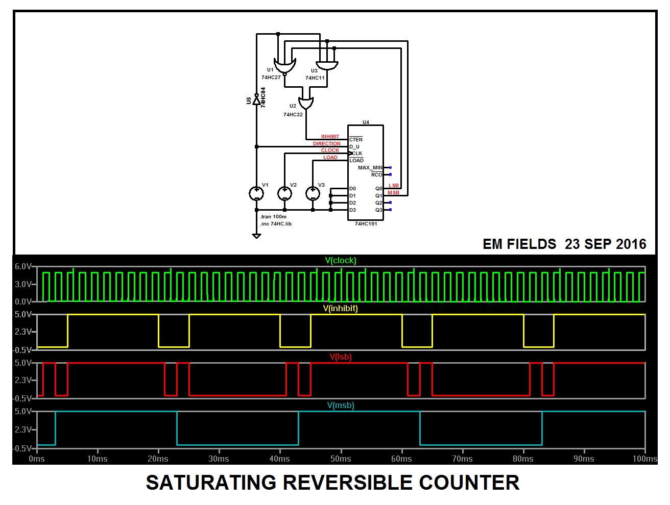
Decode the all-zeroes and the all-ones states and AND the decodes with the count direction signal, then OR the ANDed signals and connect the OR to the counter's enable, like this:

enter image description here

\$\endgroup\$

Your Answer

By clicking “Post Your Answer”, you agree to our terms of service and acknowledge you have read our privacy policy.

Not the answer you're looking for? Browse other questions tagged or ask your own question.