3
\$\begingroup\$

I am working with an Atmel ATMEGA32U4 microcontroller - datasheet here with a 16 MHz crystal for system clock.

From my understanding, this chip has a 'Divide clock by 8' fuse programmed from the factory, effectively making my system clock 2 MHz. (Page 348 of datasheet. CKDIV8 (bit 7) default value is 0, programmed).

I would like to confirm my system clock speed, so I wrote some code to output a pin low, delay one clock cycle, and then put the pin high again. Measuring the time the pin is low should equal one clock cycle.

Here is the code I used to accomplish this:

//Set PORT E as output
DDRE = 0xFF;

asm volatile("nop\n\t"::); 
PORTE |= 1<<2;  

asm volatile("nop\n\t"::); 
PORTE &=~ (1<<2);   

asm volatile("nop\n\t"::); 
PORTE |= 1<<2;  

asm volatile("nop\n\t"::); 
PORTE &=~ (1<<2);

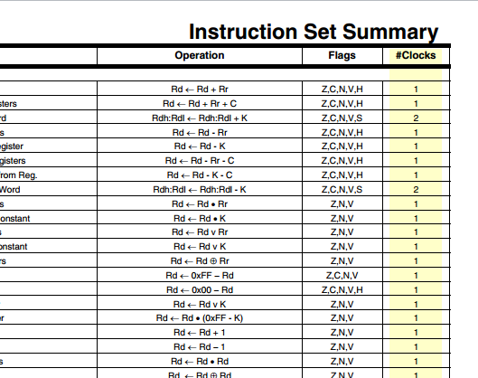
A 'nop' is equal to one clock cycle, according to the AVR instruction set manual, page 108.

Based on this information, I would assume a 'nop' instruction to take 500 nanoseconds. Is this assumption correct? (16 MHz/8 = 2 MHz. \$\frac1{2MHz}\$ = 500ns)

Here is a scope plot of my findings: enter image description here
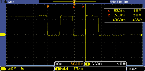
It would appear a 'nop' execution time is only 200ns (5 MHz) I would expect there to be some additional overhead using C to set the port high/low, so 500ns is actually the minimum time I would expect the pin to be low. But as you can see from my measurement cursors 'a' and 'b', its not even close to 500ns.

Can anyone explain whats going on?
Is there an error in my method?
Am I missing something 'face-palming-ly' stupid? :p
Thanks for any help!

\$\endgroup\$
3
  • 1
    \$\begingroup\$ How are you compiling this code? Even with volatile, GCC will still move those assembly statements around per gcc.gnu.org/onlinedocs/gcc/Extended-Asm.html if you have optimization turned on (anything other than -O0). \$\endgroup\$ Commented May 15, 2012 at 1:27
  • \$\begingroup\$ Compiled with AVR GCC, optimized for size (-Os), which is apparently the default setting. I will see what turning optimizations off does. \$\endgroup\$
    – dext0rb
    Commented May 15, 2012 at 2:57
  • 1
    \$\begingroup\$ compiling and then disassembling your code in my head leads to out DDRE, 0xFF; nop; sbi PORTB, 2; nop; cbi PORTB, 2; nop; sbi PORTB, 2; nop; cbi PORTB, 2; since these are all 1-cycle instructions, the time between output changes should be 2 cycles (one for the nop, one for sbi/cbi). however, your compiler might optimize the nops away or be not smart enough to use sbi and cbi \$\endgroup\$ Commented May 15, 2012 at 11:57

3 Answers 3

4
\$\begingroup\$

This is a bad approach. Ideally you would measure a very large number of NOP commands - say, one million - instead of just one. I think that's the first foolish thing I can find. I would not be very surprised if your number changes right after you implement that change.

Also, can you view the disassembly of your C code? I wouldn't even try to judge the timing without seeing exactly what assembly code was generated from my C code. I would try to work backwards from the assembly to calculate what the execution time should be (via the instruction set manual you found). That way you can see if the scope measurement is off by a little or by a lot. A little might mean you made a math error. A lot might mean one of your assumptions is wrong.

\$\endgroup\$
3
  • \$\begingroup\$ I'm guessing I'd want a number like a million to take into account clock stability(parts per million)? Also, good suggestion about looking at the disassembly. I don't know how to do that yet but I'll figure it out. Then I can see for sure what instructions are running. \$\endgroup\$
    – dext0rb
    Commented May 15, 2012 at 3:19
  • 1
    \$\begingroup\$ @dext0rb Yes that's one good reason. Another reason is that the commands to toggle the external DIO take about the same time as one NOP, but not nearly the same amount of time as one million. They'll be insignificant. \$\endgroup\$
    – AngryEE
    Commented May 15, 2012 at 11:15
  • \$\begingroup\$ Thanks everyone, wish I could accept all your answers as they were all very good but this one got me thinking and digging deeper into the assembly. I followed @noah1989 suggestion of going to 'bare metal' and it helped a lot. I did 100 NOP in a row and it equals 50uS, which makes sense to me. \$\endgroup\$
    – dext0rb
    Commented May 15, 2012 at 18:50
2
\$\begingroup\$

I've verified various clock setting of an ATtiny45 a while ago with the C code below. Although not perfect with the while loop, the delay routines come are pretty well optimized with avr-gcc libraries. I call the program '1kHz.cpp'. Check with the datasheet which exact pin outputs the block wave.

#include <avr/io.h>
#include <util/delay.h>

int main(void)
{
  DDRB = 0x10;
  PORTB = 0x00;

  while (1)
  {
    PORTB = 0x00; _delay_us(500);  // pin low, then wait
    PORTB = 0x10; _delay_us(500);  // pin high, then wait
  }
}

The trick with clock is to compile the code with the proper clock setting. On Linux it looks like this, but Windows should be reasonably similar. As you see the ATtiny45 has a 1MHz factory default clock.

freq=8000000/8
baud=19200
src=1kHz.cpp
avr=attiny45
port=/dev/ttyUSB1

# Compile
avr-gcc -g -DF_CPU=$freq -Wall -Os -mmcu=$avr -c -o tmp.o $src
# Link
avr-gcc -g -DF_CPU=$freq -Wall -Os -mmcu=$avr -o tmp.elf tmp.o
# Convert to Intel .hex (required for my programmer)
avr-objcopy -j .text -j .data -O ihex tmp.elf tmp.hex
# Program the device
avrdude -p $avr -c stk500v1 -P $port -b $baud -v -U flash:w:tmp.hex

BTW experimenting with clock setting may brick your device, so be careful which fuses you set/unset. Unbricking can only be done with a high voltage programmer (which can me made with a spare Arduino).

\$\endgroup\$
1
\$\begingroup\$

If you're doing timing analysis on the level of single instructions, you must certainly look at the disassembly of your program, or wirte it in assembly in the first place. You can then tell the exact durations from the datasheet by counting cycles for each instruction:

instruction_clocks

However, if you just want to verify that the main clock frequency is correct, there is an easier solution: Just generate a low frequency output. (0.1 Hz to some kHz, depending on what you use to measure it, a blinking LED and a stopwatch might be enough.) You could use one of the 16-bit Timers for that, or just use a loop with a long busy-wait, e.g. _delay_us(). The time spent for the loop's jumps will be neglectible.

\$\endgroup\$

Your Answer

By clicking “Post Your Answer”, you agree to our terms of service and acknowledge you have read our privacy policy.

Not the answer you're looking for? Browse other questions tagged or ask your own question.