14
\$\begingroup\$

My quesiton:

Is it better practice to put same-valued capacitors in parallel of capacitors of different values to decouple the high-frequency noise caused by digital ICs?

Background

Digital IC need a decoupling capacitor close to their supply pins to ensure a stable voltage during power transients and to deal with noise (mostly to prevent noise generated by the IC to affect neighboring circuitry). It seems sensible to place a bulk capacitor (say 10-100uF), to act as an energy reservoir, and several smaller capacitors to deal with higher frequencies. The reason to place several small capacitors instead of just one is to deal with their Equivalent Series Inductance (ESL), which in practice, causes them to behave like an LC circuit.

The effect of anti-resonance

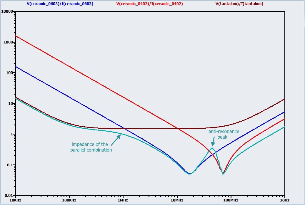
Yet, here is where best design practices and electronic myth seem to get mixed up and confusing to me. Most electronic engineers I have met like placing several decoupling capacitors of different values in parallel (with the smaller capacitors closer to the IC). The logic behind it is that the each capacitor takes care of a different noise frequency as depicted in Figure 1.

Figure 1: Impedance over frequency of three different value capacitors in parallel (cyan) vs their individual contribution (brown, blue, red). Image taken from https://www.allaboutcircuits.com/technical-articles/clean-power-for-every-ic-part-2-choosing-and-using-your-bypass-capacitors/

Figure 1: Impedance over frequency of three different value capacitors in parallel (cyan) vs their individual contribution (brown, blue, red). Image taken from All About Circuits.

Note the small anti-resonance peak. It seams no major trouble , and the overall behavior of the three different capacitors in parallel is vastly superior to their individual decoupling capabilities.

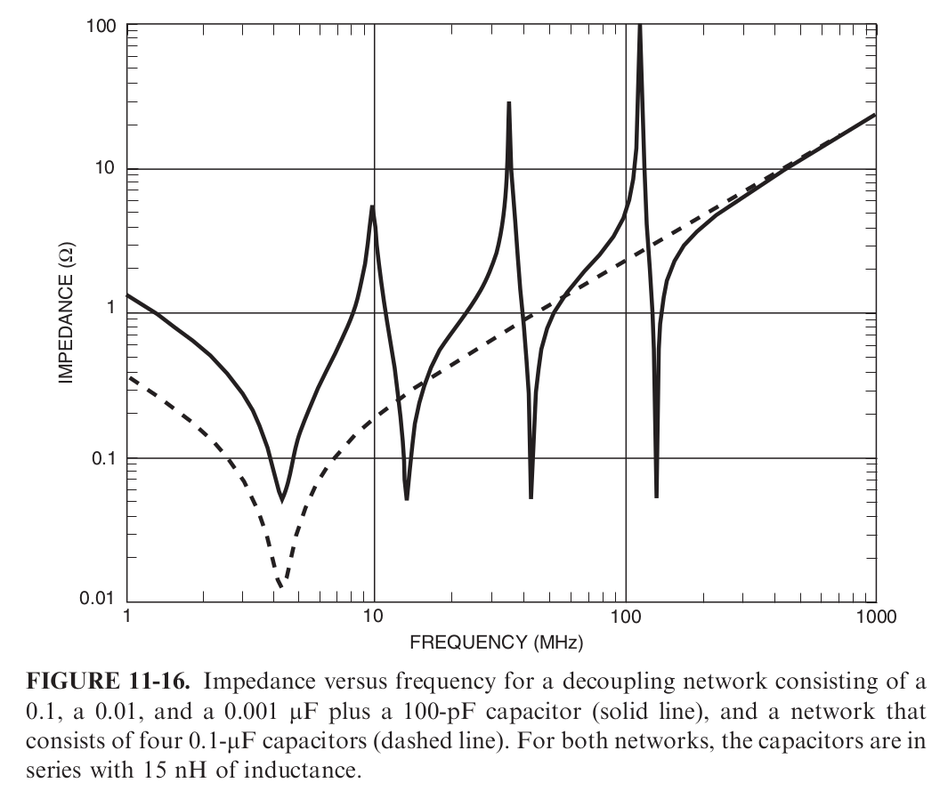
However, I have read in Electromagnetic Compatibility Engineering by [Henry W. Ott] that placing capacitors of different values may cause a much greater antiresonance-peak which can be very harmful for our designs (see Figure 2). In fact, it amplifies any noise that falls into the anti-resoance frequency range, which is corroborated by this paper.

Figure 2: from Electromagnetic Compatibility Engineering, by Henry W. Ott, section 11.4.4

Figure 2: from Electromagnetic Compatibility Engineering, by Henry W. Ott, section 11.4.4. The 15nH inductance makes reference to the capacitors ESL.

\$\endgroup\$
6
  • \$\begingroup\$ You should think of each real cap as an inductor, resistor and capacitor in series, then parallel a bunch of those up. The behaviour of the whole system depends on all three parameters and ideally needs to be tweaked until it is "good enough", which otoh depends on the requirements. "As flat as possible" thus is not a good requirement. \$\endgroup\$
    – PlasmaHH
    Commented Jul 25, 2017 at 11:47
  • \$\begingroup\$ It depends on the whole system(containing power planes,decaps etc). When multiple numbers of same value capacitors are used there are high chances of Anti resonance with power planes, same way when multiple numbers of different values capacitors are used there are high chances of anti resonance b/w different capacitor values. Bottom point we need is simulate complete system with whatever tools we have(can be simple excel/advanced tools).... \$\endgroup\$
    – user19579
    Commented Jul 25, 2017 at 12:03
  • \$\begingroup\$ I trust Henry Ott. Also, most of the time I don't have room for multiple values on every pin. And as you move the capacitor away from the pin, its value for decoupling diminishes rapidly. You need to incorporate layout factors in your simulation. Trace inductance is not negligible. \$\endgroup\$
    – user57037
    Commented Jul 25, 2017 at 16:13
  • \$\begingroup\$ In many realworld cases, the resistances: of the capacitors, the wires, the PCB foil (500 micro_ohm/square), the solder!, provides adequate dampening. For 1,000uF and 100nanoH, resonating 15.9KHz, you need 0.01 ohms for Q=1. For 0.1uF and 100nanoH, resonating 1.59MHz, you need ONE Ohm for Q=1 dampening. \$\endgroup\$ Commented Jul 26, 2017 at 17:01
  • 1
    \$\begingroup\$ smaller caps have lower ESL but higher ESR which might combat the peaking \$\endgroup\$
    – Pkennedy
    Commented Sep 26, 2019 at 22:06

5 Answers 5

2
\$\begingroup\$

The real issue at hand is the physical sizes of the caps. Back when Ott wrote this chapter, and when this rule of thumb about multiple caps was devised, you could not buy physically small caps in large values. So, they the conventional wisdom was to add big caps (with large inductance) alongside small caps (with small inductance) to get the best of both worlds. Today you can find 10uF decoupling caps in 0603 package so there is absolutely no reason to do this multiple capacitor trick.

Anyway Ott's point was that this idea does not really work in practice because the large inductance that limits the big capacitor's frequency response is still there, and in fact it ends up screwing up the smaller capacitor's frequency response too -- the different frequency responses of the individual caps do not simply subtract from each other to get the overall frequency response -- yes they are in parallel but at some frequencies you are talking about a positive impedance (large cap with large inductance) in parallel with a negative impedance (small cap with small inductance). The funny math with parallel impedance means you end up dividing by zero for some frequencies!

In laymans terms you create a tank circuit where current sloshes rapidly between the inductance of the big cap and the capacitance of the little cap instead of doing what it is supposed to do which is source/sink just the current the circuit needs to maintain constant voltage.

\$\endgroup\$
6
\$\begingroup\$

I have a bunch of observations that I decided to make into an answer and please note that I'm quite happy to spend 30 minutes doing a simulation of this if someone can precisely state what the test circuit was that produced the large anti-resonant peaks.

Firstly, I'm not sure that I follow the precise circuit of what was described by Ott.

Are the 15 nH inductors in series with each capacitor as is stated? If they are then that is clearly wrong because the smaller capacitors will have smaller ESLs. Is there any mention of the resistive loading effect of the circuit the capacitors are "smoothing"?

What are the inductances of the traces that feed the capacitors or, were the capacitors connected using earth and power planes?

In short, I'm not happy with the Ott claim based on the lack of clear circuit that can be reproduced in a sim. If a clear circuit can be made available then I'm interested!

\$\endgroup\$
2
  • \$\begingroup\$ Thank you very much for your response. As I understood Ott's chapter, he models the trace inductance and the ESL for each capacitor as a 15nH inductance. He assumes each capacitor is connected with its own trace, and I believe that he neglects the series resistance (of both the capacitor and the trace). Thus he simplifies things and models every capacitor as an ideal capacitor in series with said 15nH inductance. \$\endgroup\$ Commented Jul 25, 2017 at 13:06
  • 2
    \$\begingroup\$ @andresgongora That is my concern - he has modeled something that is unrepresentative of reality. \$\endgroup\$
    – Andy aka
    Commented Jul 25, 2017 at 13:15
6
\$\begingroup\$

You're doing pretty good on getting to the parallel resonance already. It depends on your application. If you're trying to suppress/bypass for example ethernet peaks, you should use parallel caps which have impedance dips in the fundamental frequency and some of the harmonics.

The "perfect" solution is to use low-ESL type ceramics which are usually characterized by having the pads on the long ends. These tend to have impedance over the spectrum that's as low or lower than regular MLCC chips have in their dips. They're also less vulnerable to the impedance peaks because there's so little inductance involved.

Here's a good write-up of what's going on here, a major source of these resonances are component pads, power planes and vias, not so much the capacitor itself: http://ntuemc.tw/upload/file/20120419205619a4fcf.pdf

Some people think you shouldn't aim to get your dips on the fundamental switching frequencies anyways because it allows the chip to do faster edges but I'm not sure I buy that. The impedance dip would be on the fundamental frequency, not on the higher harmonics that makes that sharp edge.

\$\endgroup\$
5
  • 1
    \$\begingroup\$ Thank you for your fast response. My specific problem is that I want to decouple a circuit with lots of PWM in it. Meaning that I have no clear fundamental frequencies I can aim at. Should I keep the capacitors with different values though? \$\endgroup\$ Commented Jul 25, 2017 at 12:35
  • \$\begingroup\$ PWM is a bit tricky. Usually it's a pretty low frequency, no? So a large ceramic (10µF or something) should cover frequenc(ies) of interest. General rule of thumb with parallering caps is that you have a "large" tank capacitor (can be electrolytic or "large" MLCC) and then a smaller capacitor to catch high frequencies which can be tuned to fundamental switching frequency of the IC (think sampling frequency, PHY signaling frequency..). Unless you have a specific reason to catch specific frequencies like the square wave harmonics, leave paralleling different size MLCC caps well enough alone. \$\endgroup\$
    – Barleyman
    Commented Jul 25, 2017 at 12:59
  • 1
    \$\begingroup\$ I think I have problems with the harmonics (very steep rises, which I can not afford to lose by damping them). Also Its high frequency (for PWM, that is) of up to 1 MHz depending on my system's configuration. EDIT: After your edit: thus, you recommend using same valued capacitors, right? \$\endgroup\$ Commented Jul 25, 2017 at 13:09
  • \$\begingroup\$ Ironic, the original upload is still up but the drive link is unavailable. \$\endgroup\$
    – Ananas_hoi
    Commented Oct 30, 2020 at 11:18
  • \$\begingroup\$ @ananas-hoi That must have been my drive holocaust a couple of years back as I had drive filling up without files to match so I basically burned everything down until I eventually got to 0 usage. \$\endgroup\$
    – Barleyman
    Commented Oct 31, 2020 at 17:28
2
\$\begingroup\$

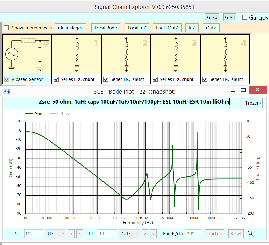
Summary: the individual capacitors need dampening; for 100uF caps, the solder and PCB foil may suffice (10milliOhm, if L = 10nH); for 1uF, use 0.1 ohm; for 10nF, use 1 ohm, etc.

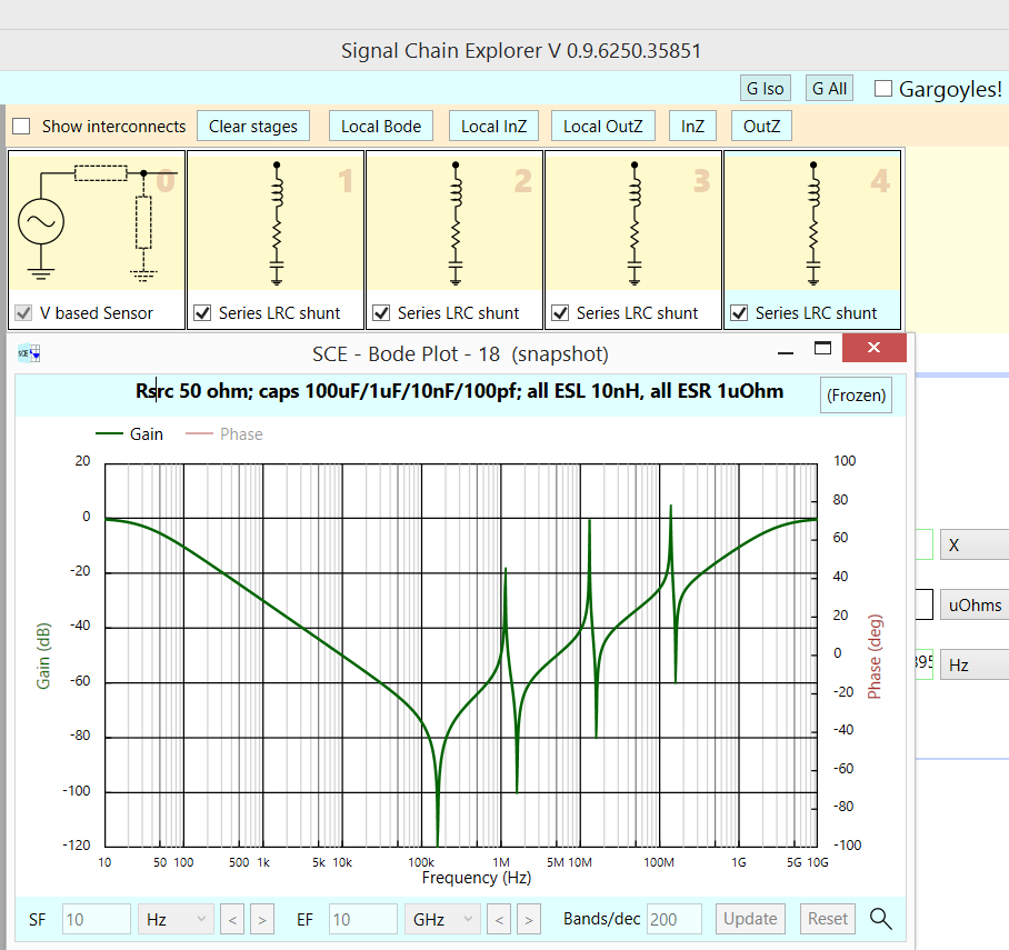
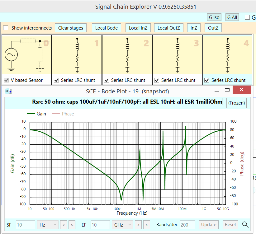
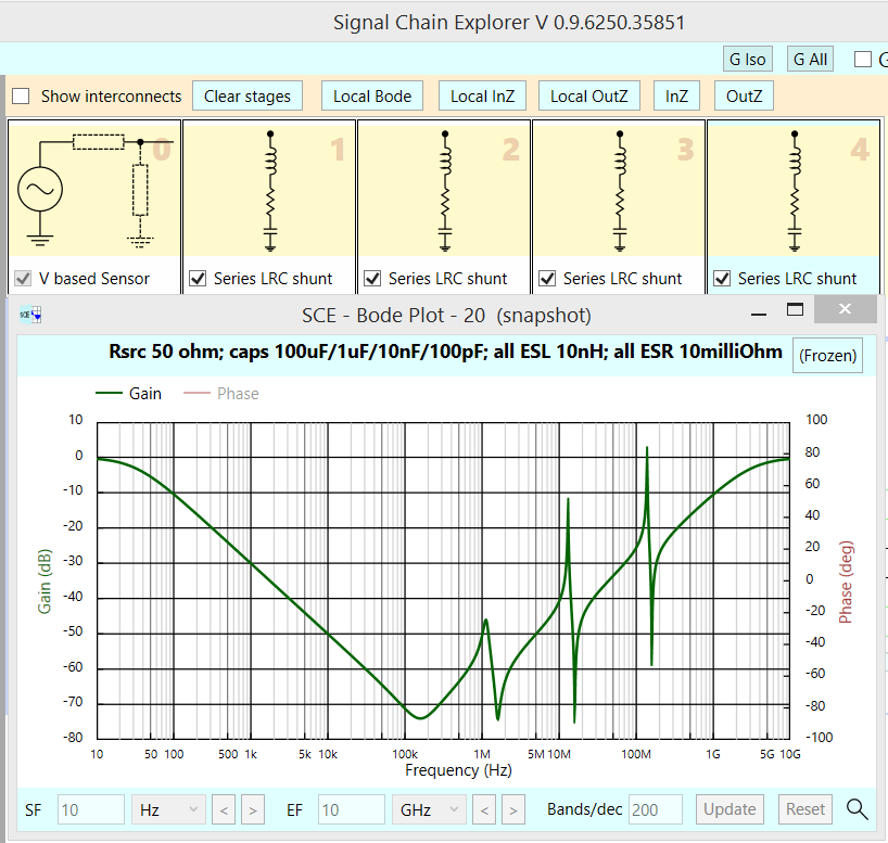
Here with 4 capacitors, 100U/1U/10n/100p and 10nH ESL, the peaking depends on the losses in each cap {I consider sqrt(L/C) a good start; thus 10nH and 10pF needs 3.1 ohms, which I have not used here; however, 10nH and 100uF need 10 milliohm, which is illustrated in the 3rd screenshot.}

Lets examine this response, with 1 microOhm ESR in each cap. Notice the lowest dip is to -120dB. Zsource is only 50 Ohms. enter image description here

Now this response, with 1 milliohm ESR in each cap. Zsource is 50 Ohms.

enter image description here

And now 10 milliohm ESR for each cap, Zsource is 50 Ohms.

enter image description here

And with 10milliOhm in each cap, with the Zsource now 1uH + 50 ohms

enter image description here

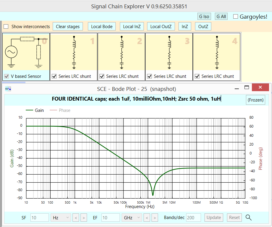
Here is (requested) SCE sim [available at robustcircuitdesign.com for free] with 4 identical 1UF caps, each with 10nH ESL and 10milliOhms. There are NO PEAKS, because the 10milliOhm dampens those peaks. [or is the Zsource, of 50 ohms and 1uH, what dampens??]

enter image description here

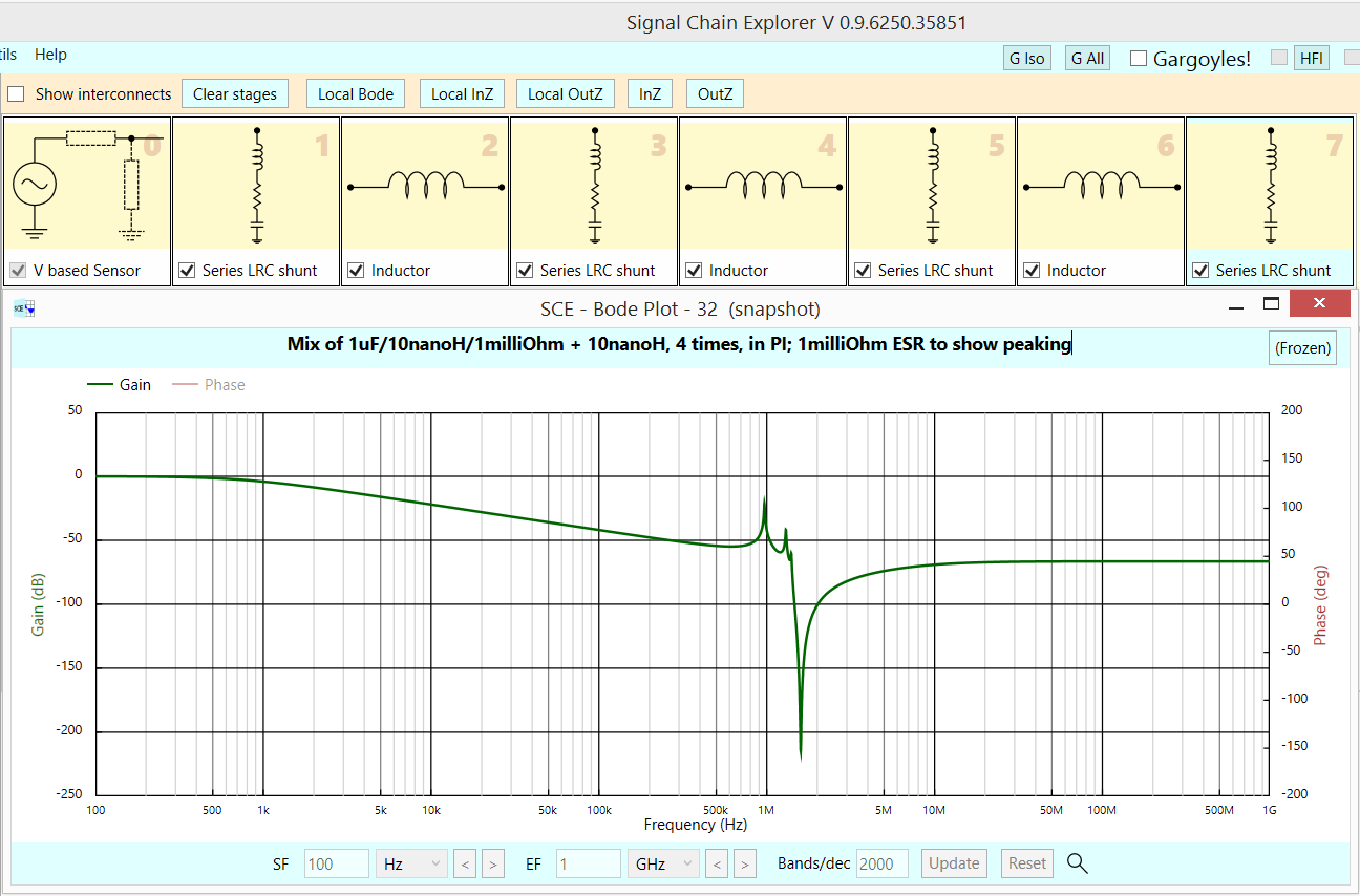
In prior sim, there was no peaking. So I insert 3 inductors between the 4 caps. Now a sim of those 4 caps + 3 inductors (PCB foil, 10nH each). Notice the peaking returns (the ESR is only 1 ONE milliohm, to show peaking), at -20dB.

enter image description here

\$\endgroup\$
7
  • 1
    \$\begingroup\$ Thank you very much! Your simulations clearly show that, as stated by Ott, we can expect very high anti-resonance peaks at certain frequencies (here 1.05MHz, 10.5MHz, and 105MHz). Could you also simulate what happens when the capacitors are the same value to compare? With say 10mOhm ESR. I have no access to Signal Chain Explorer (sadly). \$\endgroup\$ Commented Jul 26, 2017 at 7:55
  • 1
    \$\begingroup\$ Signal Chain Explorer is free to download. \$\endgroup\$ Commented Jul 26, 2017 at 16:24
  • 1
    \$\begingroup\$ I don't think using 1R dampening cap would make sense as it'd essentially negate the bypass functionality you want with the capacitor to start with. \$\endgroup\$
    – Barleyman
    Commented Sep 8, 2017 at 14:18
  • 1
    \$\begingroup\$ @Barleyman I'm shying away from placing extra impedance on my application's power path. I've been running similar simulations to those of analogsystemsrf, and I'm seeing that antiresonance is more complex than expected. \$\endgroup\$ Commented Oct 10, 2017 at 7:51
  • 3
    \$\begingroup\$ Aren't those simulation values a little bit exaggerated (unrealistically bad)? ESR values are usually in range of 10's milliohms (0402 and 0603 caps) not 1 milliohm. ESL values are in range of 100's of picohenrys, not 10nH. So you calculated with extremely high Q, which made that anti-resonance look very ugly. I'm looking to some caps specifications and making some simulations so I wonder if I make something wrong or what, but those values look very different from yours. \$\endgroup\$ Commented Jan 25, 2021 at 14:39
1
\$\begingroup\$

To complement others' answers:

Same value caps can also resonate together if you consider they are connected together with non-zero inductance traces or planes. You most likely won't get a large resonance peak in the impedance, but you will get a bit of circulating current in the power/ground as the caps ring together.

\$\endgroup\$

Your Answer

By clicking “Post Your Answer”, you agree to our terms of service and acknowledge you have read our privacy policy.

Not the answer you're looking for? Browse other questions tagged or ask your own question.