I'm currently making a PCB with 2 ethernet ports and a CPU running at 200+ Mhz. This isn't the fastest PCB by any means and I don't foresee any issues with the placements, however in the future I might want to know how to do this properly.
And before anyone asks, yes I did in fact check the hundreds of other posts for this subject. The problem is that it's conflicting each other every other post. One person says the loop matters, the next says don't do vias, the next says power should hit cap first then chip etc.... It's confusing as hell.
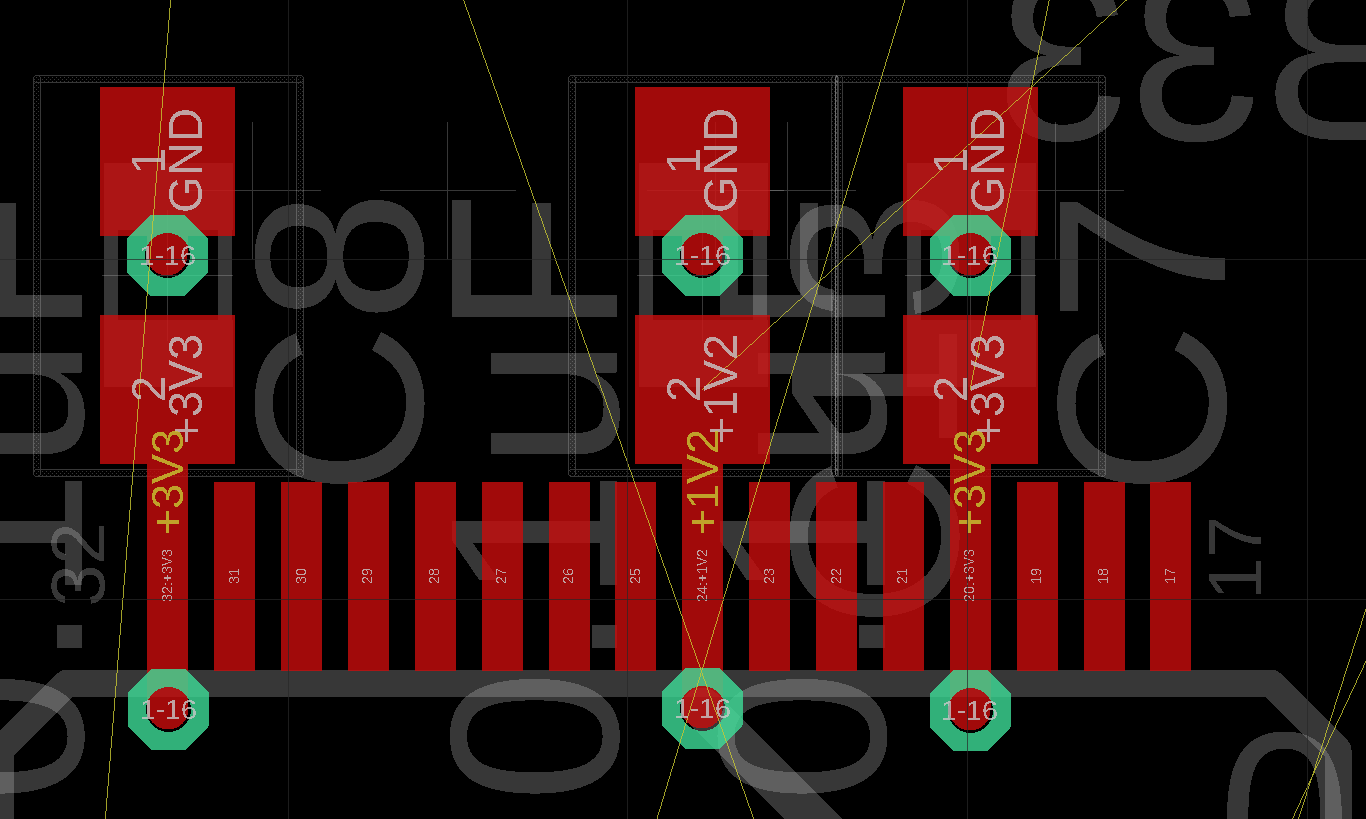
This is kind of the style I'm using for this particular board:
It's a 4 layer PCB with signal-ground-power-signal layers. I simply route the vias to these massive planes in the picture(sidenote: is it ok to occasionally route other voltages over the power plane?). I'm also thinking of moving the vias on the inside of the chip directly on top of the SMD pads but I'm not sure if the manufacturer(Eurocircuits in this case) allows this.
What is the correct way of placing decoupling capacitors?

