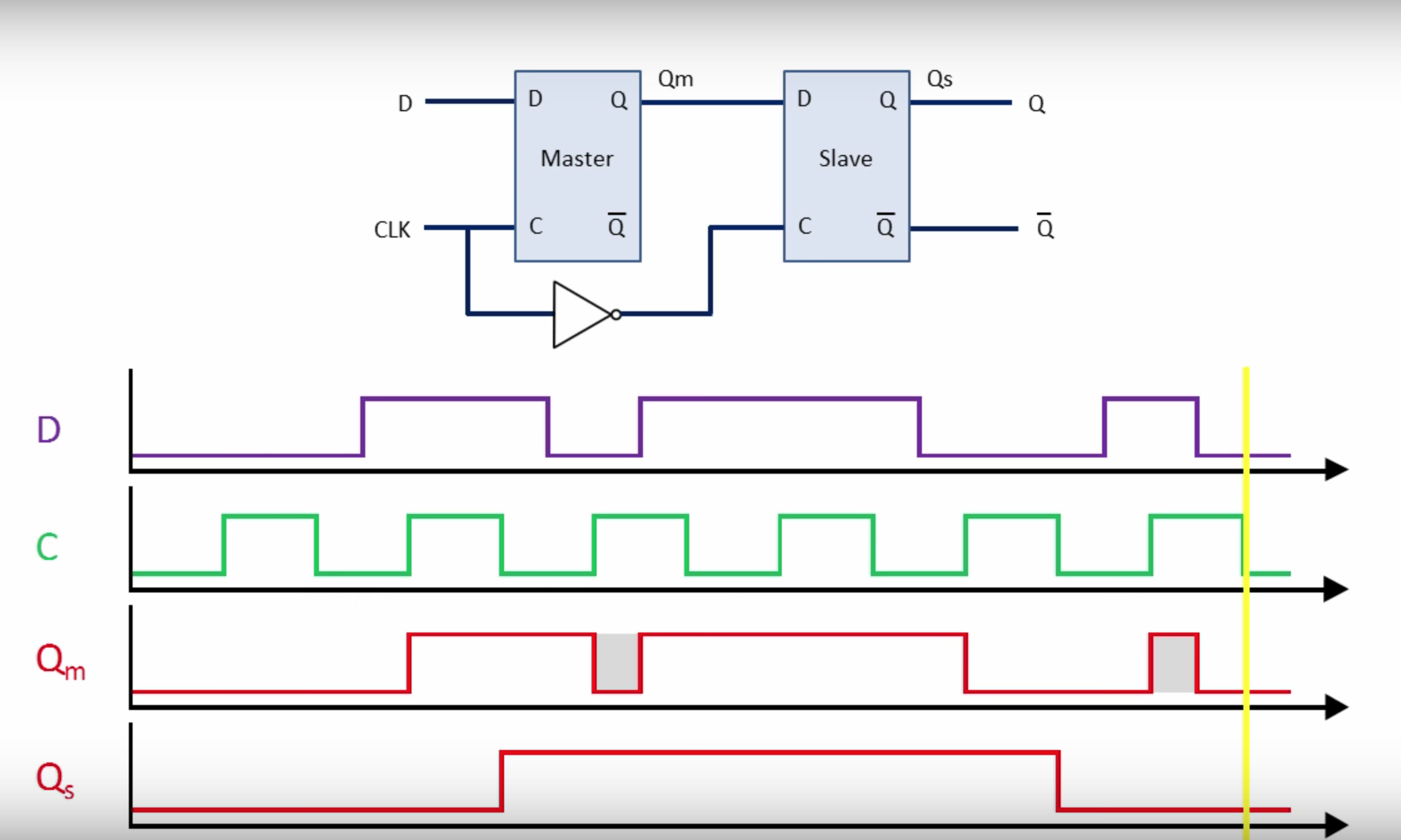
The master slave D flip-flop, is it used to prevent glitches in the data signal? Say, when there is a transition between LOW -> HIGH or HIGH -> LOW in the data signal when clock signal is at level ?
2 Answers
What you have in the figure and waveforms is a positive D Latch (Master Latch) cascaded with a negative D Latch (Slave Latch). Together, this Master-Slave configuration act as a negative edge-triggered D Flip-flop.
Latches are level-sensitive and simply propagates the data at the input when they are in transparent mode (i.e., when clock stays high for positive latch, or when clock stays low for negative latch). If some glitches happen, while in transparent mode, it is propagated as well (Observe D, Qm, CLK waves to see how Master Latch works).
Master-Slave configuration solves the above problem by cascading the latches and forming an edge-triggered D Flip-flop. A Flip-flop captures and propagates the input data only at the edge of the clock transition (here, the negative edge of CLK). Until the next clock edge, Further transitions/glitches in the data are not reflected at the output. So, that is why the third pulse of Qm (glitch as you say) was not propagated to the output Qs. At the next negative edge, Qm is captured as low, and hence Qs remains low as well.
You can read the section D-Flip-flop here to understand the full working of this configuration.
Your questions are a bit confusing. Good English takes time. What the chart is showing is that brief glitch's in the data input that are less than 1 clock cycle are ignored.
You will notice the output is a cleaned up version of the input D. D is show as having random negative or logic '0' values, perhaps as a result of a long transmission line picking up some noise. A simple 2 pole running filter ignores both brief zeros or ones. Putting it another way the D input has to have a duration at least one clock cycle in length to pass through the filter, whether it is logic '1' or '0'.
The inverter cuts the filter delay time in half, so rising edge causes data to enter first flip-flop, and falling edge allows data to enter the second flip-flop.
In this case D is logic '1' long enough to last 3 full clock cycles at the output. At point Qm, two logic pulses are grayed out, showing they are too short to pass through the filter.

