1
\$\begingroup\$

enter image description here

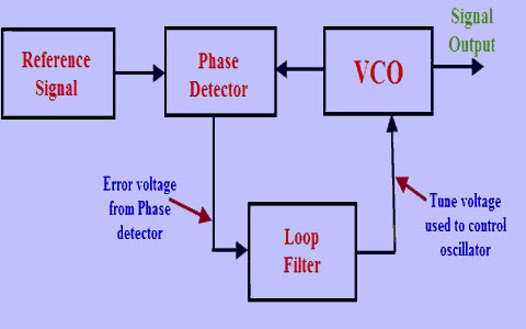
  1. How is it possible that the Signal Output will have the same frequencies as the Reference Signal?
    \$f_1\$, Frequency of the Reference Signal;\$f_2\$, Frequency of the VCO.
    1. Let's assume that \$f_1>f_2\$, so the phase detector will create a positive voltage \$V_1\$
    2. At this point \$V_1\$ will ensure that the VCO will increase his frequency of oscillation.
    3. At this point \$f_1=f_2\$, and this will make \$V_1=0\$, but if \$V_1=0\$, then \$f_2\$ will drop.
    4. If \$f_2\$ drops, \$f_1\$ will become again \$>f_2\$, and \$V_1\$ will be positive.

In according to this reasoning this circuit will create an oscillation, where am I wrong, (Since this circuit will create a very stable Signal Output with the same frequency of the Reference)?

  1. Why this circuit need an error in the phase for create a lock and so Phase1 must be not equal to Phase2?
  2. What will happen if \$f_2>f_1\$, will the Phase Detector create a Negative Voltage?
\$\endgroup\$
4
  • 1
    \$\begingroup\$ the error voltage is not DC .... moodle.insa-toulouse.fr/pluginfile.php/2665/mod_resource/… \$\endgroup\$
    – jsotola
    Commented Jun 1, 2019 at 21:01
  • \$\begingroup\$ as @jsotola said, the phase detector detects phase, not frequency. Phase is a linear function of frequency difference. \$\endgroup\$ Commented Jun 1, 2019 at 22:20
  • 1
    \$\begingroup\$ Your concern is well-founded, but is a common issue. Almost ANY feedback loop contains the seeds of oscillation - it is up to the designer to avoid it. In your case, the loop filter must be designed properly. If it is underdamped, any change in open-loop VCO characteristic may produce unstable operation, usually only temporary. \$\endgroup\$ Commented Jun 2, 2019 at 0:14
  • 1
    \$\begingroup\$ Which frequency is \$f_1\$ and which is \$f_2\$? Your block diagram doesn't say which is which. Also, what's \$V_1\$? \$\endgroup\$
    – The Photon
    Commented Jun 2, 2019 at 2:13

2 Answers 2

1
\$\begingroup\$

Simplistically, the loop filter can contain an integrating element, so that the output of the phase detector going to zero doesn't necessarily mean the control voltage of the VCO will be zero.

To make things more complex, remember that phase is the integral of frequency, so by using a phase detector rather than a frequency detector, you've already included an integrating device in your control loop. The loop filter will likely need to include both integrating and differentiating components to keep the loop stable, while also allowing the loop to react quickly to disturbances in the VCO behavior, thus minimizing phase noise of the output.

\$\endgroup\$
-1
\$\begingroup\$

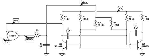
my first 'pll' was like this

schematic

simulate this circuit – Schematic created using CircuitLab

To get a lock, I had to vary the input "Fref". I then noted a varying input duty cycle would change the delays between input edges (Fref edges) and the astable-oscillator edges.

Within a few years I was deep into non -EXOR PFDs at 20MHz (for data recovery in telemetry) and 2-pole-1-zero loop filters, with variable Icharge_pump to allow adjusting the loop bandwidth as SNR and Jitter varied. Because our task was data-recovery, the timing error budgets were low nanoseconds; we used ECL in the PFD (phase frequency detector) and 2GHz diffpairs in the charge pumps --- your national defence $ at work.

\$\endgroup\$

Your Answer

By clicking “Post Your Answer”, you agree to our terms of service and acknowledge you have read our privacy policy.

Not the answer you're looking for? Browse other questions tagged or ask your own question.