3
\$\begingroup\$

I have a basic question regarding PLLs and how they actually achieve lock.

I was told that the PLLs go into the lock when the output of a phase detector is zero, therefore to drive VCO an integrator is used between the phase detector and the VCO to keep the voltage at a constant level.

However, I am struggling to understand how exactly the integrator keeps that voltage on a constant level.

If the input of an integrator drops to zero then its output over time will also drop to zero as it is an integral of input, no? I even ran Multisim simulations with an integrator to understand its behaviour better. When I was applied a sine wave to it that would mimic characteristics of an analogue multiplier phase detector, every time I turned off the voltage on the rising edge when phase difference = pi/2, the integrator's output would drop to zero after a few seconds.

\$\endgroup\$
1
  • \$\begingroup\$ An ideal integrator has infinite gain at DC, so it will tend to drive the error to zero, causing the VCO to output the correct value. (Assuming the loop is compensated properly) \$\endgroup\$
    – John D
    Commented Oct 23, 2021 at 18:27

3 Answers 3

4
\$\begingroup\$

If the input of an integrator drops to zero then its output over time will also drop to zero as it is an integral of input, no?

An ideal integrator would "store" the last value and it won't change over time. A real integrator would drift, not necessarily to zero, its output voltage could also grow up to the positive rail or drop down to the negative rail. It could drop to near zero volts if the negative rail is zero volts, only.

However, I am struggling to understand how exactly the integrator keeps that voltage on a constant level.

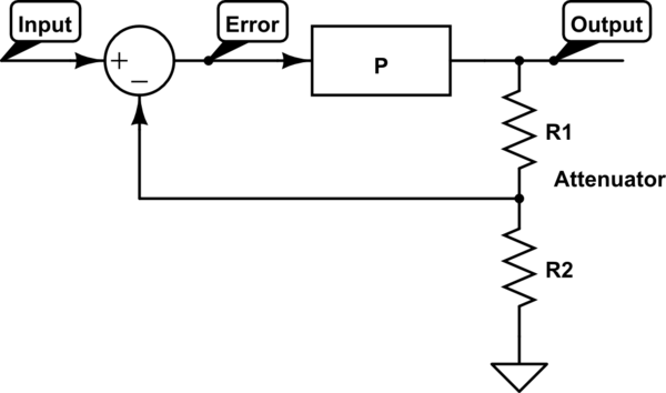
I am going to do some analogy with an audio amplifier:

schematic

simulate this circuit – Schematic created using CircuitLab

The output voltage is attenuated by an resistive divider, let say to 1/10-th of output value. This is subtracted from the input signal and then amplified. Practically we have an amplifier that amplifies the input voltage by 10.

Theoretically we have a device that amplifies the error between input and output signal. The error is the "food" for the amplifier, without it the output would be zero. So even theoretically, the output can't never be equal to input x 10, you always get a distorted signal.

If you compare the PLL, the phase difference is the "food" for the PI compensator. The integrator would of course drift over time if the error is zero, but as it drifts the phase difference changes, the error gets bigger and then the integrator is "refilled"

The error is never zero, but very close to it.

\$\endgroup\$
1
  • \$\begingroup\$ Such an intuitive answer. Thank you! \$\endgroup\$
    – Matt_LDN
    Commented Oct 23, 2021 at 20:42
2
\$\begingroup\$

The function of the integrator is to store a history of the input. This means that when the input is zero, the integrator is supposed to not change its voltage. The voltage at that moment is the correct voltage to put the VCO where it is supposed to be.

If the integrator voltage begins to drift for any reason, the VCO phase will change, and the phase detector will output an error voltage that drives the integrator to go back to the correct voltage.

\$\endgroup\$
0
\$\begingroup\$

If the input of an integrator drops to zero then its output over time will also drop to zero as it is an integral of input, no?

No, if the input voltage drops to zero, an integrator has nothing to integrate and its output stops at whatever level it was when the input dropped to 0 volts.

every time I turned off the voltage on the rising edge when phase difference = pi/2, the integrator's output would drop to zero after few seconds.

That is at best "non-ideal". At worst it's flawed. In reality it's probably your integrator circuit having some non-ideal components or, some error somewhere.

\$\endgroup\$
3
  • \$\begingroup\$ Great, thank you for the response. That's the simulation I was using multisim.com/content/DJoiPxiirFBDnN8WtgTLcg/op-amp-integrator When you turn off the input, the output just drops to zero. \$\endgroup\$
    – Matt_LDN
    Commented Oct 23, 2021 at 18:34
  • 1
    \$\begingroup\$ There's a 10K resistor across the integrator cap, so naturally it's not an ideal integrator and the output will return to zero. Also, the DC gain of the circuit is only 10, so it's not even a very good approximation of an integrator. For simulation purposes try making the 10K resistor 1 meg or so. But you still have to make sure your loop is stable with the additional gain. \$\endgroup\$
    – John D
    Commented Oct 23, 2021 at 18:43
  • \$\begingroup\$ Listen, when you have a phase locked-loop, you don't need the feedback resistor so dump it because, even with a massive DC open-loop gain (circa 100,000 for an op-amp), the slug caused by the integration capacitor will usually mean you can avoid instability. At the very least, make it one hundred times higher and see how things pan out @Matt_LDN \$\endgroup\$
    – Andy aka
    Commented Oct 23, 2021 at 19:55

Your Answer

By clicking “Post Your Answer”, you agree to our terms of service and acknowledge you have read our privacy policy.

Not the answer you're looking for? Browse other questions tagged or ask your own question.