0
\$\begingroup\$

The Logic Gate

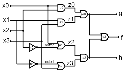
Here's as far as I've gotten with this:

module Lab2pl(input x3, x2, x1, x0, output f, g, h);
  wire z3, z2, z1, z0, notx2, notx1;

  and
  a0(x0, x2, z0),
  a1(x1, x3, z1),
  a2(z2, z3, h, f);

  not
  n0(x2, notx2),
  n1(x1, notx1);


  or
  o0(z0, z1, g, f),
  o1(notx2, x0, z2),
  o2(notx1, x3, z3),
  o3(f);
Endmodule

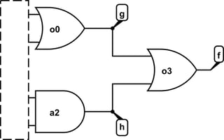
It really doesn't make any sense to me how the wires going from o0/a2 into o3 aren't labeled. I can't find any helpful tutorials or resources and this is due tonight. Any help would be HUGELY appreciated.

\$\endgroup\$

3 Answers 3

2
\$\begingroup\$

It really doesn't make any sense to me how the wires going from o0/a2 into o3 aren't labeled.

They are labelled -- they're g and h.

Here's a redrawn version of that part of the schematic which might make it clearer what is intended:

schematic

simulate this circuit – Schematic created using CircuitLab

Fix the instantiations of o0, a2, and o3 such that there are two inputs and one output for each one. Besides that, what you've got looks correct.

\$\endgroup\$
1
\$\begingroup\$

Your port order on the Verilog primitives is incorrect.

The first port for all Verilog primitives is an output. Multiple inputs are allowed for and, nand, nor, or, xor, xnor. Multiple outputs is supported from buf and not with the last port treated a the input.

The wire form o0 to o3 is defined: g. The wire form a2 to o3 is also defined: h.

\$\endgroup\$
0
\$\begingroup\$

Are you allowed to use assign statements? This would yield a more concise, C language-like representation of your logic.

Then again, if the point of the exercise is to use the predefined functions in Verilog (more here: http://verilog.renerta.com/source/vrg00003.htm) then you wouldn't use assign.

That said, how to check this then?

All the gates are 2-in 1-out with a variable list (in,in,out) and two inverters (in, out). Check the gate signal lists carefully. You will notice something off about several of them.

And, yes, the inputs to gate o3 do have labels. You created them in your wire list, and assigned them to a signal level with the outputs from gates o0 and a2.

\$\endgroup\$
1
  • 1
    \$\begingroup\$ I get the sense that this exercise is intended to demonstrate to the student how structural Verilog can get clunky when used this way. :) \$\endgroup\$
    – user39382
    Commented Sep 13, 2019 at 3:04

Your Answer

By clicking “Post Your Answer”, you agree to our terms of service and acknowledge you have read our privacy policy.

Not the answer you're looking for? Browse other questions tagged or ask your own question.