0
\$\begingroup\$

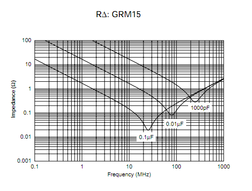
Here is frequency-impedance curve for real capacitor.

enter image description here

The basic profile of a dip and then increase in the impedance is caused by the ESL. It is not possible to get rid of ESL and it is a non-ideal property of real capacitor. Thus, regardless of material and capacitor geometry used, this shape of the curve shall remain.

Now my question is, decoupling capacitors are used to mitigate high frequency noise on the power supply rails. But if they end up having such high impedance at high frequencies, it kind of defeats the purpose of using capacitors to filter high frequency noise on power supply rails. So why do we still use capacitors to filter high frequency noise on power supply rails?

\$\endgroup\$
3
  • \$\begingroup\$ If not a capacitor what else would you use to provide a low impedance path for noise? \$\endgroup\$ Commented May 31, 2023 at 1:55
  • 2
    \$\begingroup\$ 0.3 ohm at 100MHz is considered "high"? Have you seen electronics.stackexchange.com/a/298817/311631 or electronics.stackexchange.com/a/304997/311631 ? (Note that both plots potentially miss the parallel resonance that can be quite high impedance if values are poorly chosen.) \$\endgroup\$ Commented May 31, 2023 at 1:58
  • \$\begingroup\$ I am not talking about specific frequency. I am talking about the impedance profile. Also, I am not at all aware of the frequency range of the noise that is formed on a power supply when dealing with digital ICs like FPGAs and microprocessors. \$\endgroup\$
    – quantum231
    Commented May 31, 2023 at 16:42

4 Answers 4

1
\$\begingroup\$

The reason why capacitors are used is simply because even a non-ideal capacitor with some ESL connected directly to chip supply pins is still much better than not having a capacitor at all or having it far away behind long PCB tracks.

Just like any wires, also PCB tracks are wires and they have inductance. Assuming that a 1 inch long PCB track has about 20 nH inductance, that's 1 ohms at 10 MHz, 12 ohms at 100 MHz, and 120 ohms at 1000 MHz.

That's about 100x more than the capacitor you show, so the capacitor needs to be right at the chip, not one inch away, to be useful at high frequencies.

\$\endgroup\$
1
  • \$\begingroup\$ Since we know that at high frequencies, the ESL will dominate, what is the implication for power integrity and power distribution network? \$\endgroup\$
    – quantum231
    Commented May 31, 2023 at 19:29
3
\$\begingroup\$

The capacitor itself has negligible impedance at high frequencies. Or at least, the notion of "inductance" is meaningless for an isolated capacitor because no current can flow through an isolated device.

The problem is that current has to flow through it and through the load, if you are going to use this capacitor to provide high frequency supply stabilization. This forms an inevitable current loop causing the ESL. So I would say that the ESL is not a fundamental property of the capacitor, but of its connection.

If you need better performance at high frequency, you as a board designer must improve (tighten) this loop.

  • Overlay trace and return trace in a tight layer stack
  • Use wide traces and many vias
  • Use many loops in parallel (via the placement of many capacitors)
  • As an IC designer, use interdigitated supply and return pins and on-chip capacitance
\$\endgroup\$
2
\$\begingroup\$

Ideally your supply rail has a low impedance at every frequency of interest. And different components take care of different frequency ranges:

The voltage regulator offers low impedance at frequencies from DC to the kHz region. Then large bulk capacitors might take over up to maybe 1 MHz. Above 1 MHz smaller ceramic capacitors step in up to maybe 100 MHz. For even larger frequencies the capacitance of your PCB's power plane might offer low impedance and after that the on-die capacitance of your chip.

Depending on your circuit you only need a subset of these components.

Because of the graph you have posted I'm guessing your question is about ceramic capacitors. And the answer is simply that ceramic capacitors can only take care of a specific frequency range.

Maybe - because of your circuit - you don't care what's happening in frequency ranges where your ceramics (or their connection to the PDN and/or power pins of your device respectively) become inductive.

If you do care, you'll need additional measures.

\$\endgroup\$
2
\$\begingroup\$

So why do we still use capacitors to filter high frequency noise on power supply rails?

Very good question, but first you need to define what you mean by "high" for the frequency of interest.

From EMI perspective, up to 1 GHz is what we are generally interested in. But there's an allowed amount emission for the entire range (e.g. EN 55015). So actually, we may not have to filter out the frequencies above, say, 100 MHz but we try to keep the emission as low as acceptable (via layout optimisation, component selection, placement, etc) for the target standard(s).


When it comes to filtering, a capacitor on its own is not always sufficient for the frequency (or range) of interest. Because the effect of the capacitor depends on the source impedance. If the signal source impedance is low enough (e.g. 1 milliohm) then any capacitor will be able to do almost nothing, so all of the signals will just past through without any filtering at all.

So we combine it with chokes or beads or even with resistors if the signal source impedance is really low. Or we combine it with different value capacitors in parallel if the signal source impedance is relatively high.

Look at the impedance graph in your question: Although 100n does a pretty good job for the entire range (the impedance doesn't go above 20 Ohms which might be pretty low for most applications), it shows 250 milliohms at 100 MHz. If this is still high then we can add a 6n8 or 8n2 (judging from the 10n graph) in parallel to decrease the net impedance further. For higher frequencies, we add further low capacitances (e.g. 100 pF or 10 pF).

\$\endgroup\$

Your Answer

By clicking “Post Your Answer”, you agree to our terms of service and acknowledge you have read our privacy policy.

Not the answer you're looking for? Browse other questions tagged or ask your own question.