0
\$\begingroup\$

I've created a circuit that gets a 3-bit code and changes it to either from binary to gray code (if c is low) or from gray code to binary (if c is high):

enter image description here

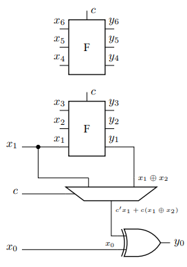
now for the question with the 7 bit, this is what I came up with (the F component is the circuit from before), I wanted to know if I'm right in my thinking or if I might miss something:

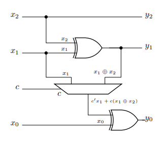
enter image description here

\$\endgroup\$
0

2 Answers 2

1
\$\begingroup\$

Try to create separate 7-bit Gray to binary and binary to Gray converters first (or start with 4-bit convertors to make it simple). Look at the similarities between the two, and it should be obvious where you would add the MUXs.

\$\endgroup\$
1
  • 1
    \$\begingroup\$ from what I see the pattern repeats, I can't post here a pic but the pattern of taking the input and output of the xor and driving them through a MUX and into the top input of the next xor and bit, repeat for however many bits. I think I got it, thanks for the help! \$\endgroup\$
    – Nate3384
    Commented Jun 22 at 20:11
0
\$\begingroup\$

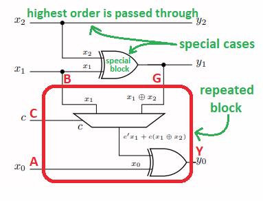
If you look at your own logic block, it's easy to see that it only has four inputs and one output.

enter image description here

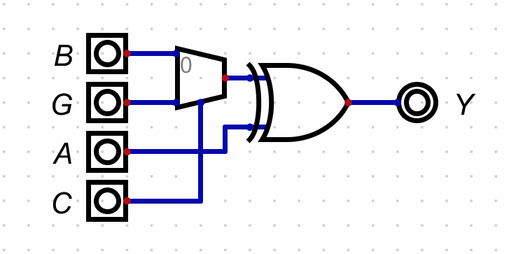
So just make a module out of the red-circled portion, like this:

enter image description here

I'll call it GB for now.

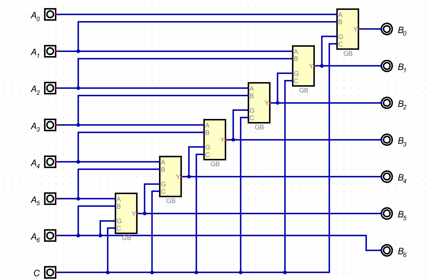
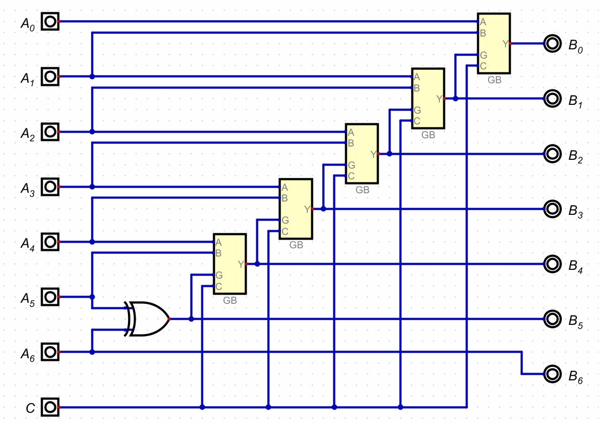
Then the 7-bit converter would look like:

enter image description here

Except that the highest order GB can be replaced with a simple XOR, since it's G input doesn't connect to a higher-order bit's stage and the C input can be ignored since it selects the same thing either way:

enter image description here

You were just on the verge of getting there, I suspect.

I haven't tested this as I trust you already did good work before. But it looks correct to me. That said, you shouldn't trust what I write. Verify it.

\$\endgroup\$
7
  • \$\begingroup\$ just so we're on the same page, A6 for you is the MSB, right? I'm thinking through this one, I'll respond when I understand it \$\endgroup\$
    – Nate3384
    Commented Jun 22 at 19:39
  • \$\begingroup\$ @Nate3384 Yes. A6 is the highest order bit. I think I said something along those lines in the text, too. I have since tested it for all 256 input permutations. It passed the testing. \$\endgroup\$ Commented Jun 22 at 19:48
  • \$\begingroup\$ @Nate3384 it's not difficult to see from your own diagram. Copy and paste the red section down below itself. Hook up the new G to the existing y0, the new A to the existing x0, connect the new C to the existing C, and name the new A as x(-1) and the new Y as y(-1). Then add 1 to the index of all inputs and outputs to rebase on zero again. Etc. \$\endgroup\$ Commented Jun 22 at 20:04
  • \$\begingroup\$ I'm sorry but your explanation was too confusing for me, and I couldn't understand it, it's probably right tho, thanks anyway, especially for the time you dedicated \$\endgroup\$
    – Nate3384
    Commented Jun 22 at 20:15
  • \$\begingroup\$ @Nate3384 hmm. Don't let yourself be confused by the three outputs of your starting module. It is providing three outputs because there are three inputs to handle. You should know by inspection that the highest order bit is always just passed through. You may not so easily see that the next highest order bit only needs an XOR. All remaining bits require the mux plus XOR. There is another way to show this with two pictures laid on top of each other. Perhaps I'll add that to see if it shakes anything loose. But perhaps that's not needed. \$\endgroup\$ Commented Jun 22 at 20:28

Your Answer

By clicking “Post Your Answer”, you agree to our terms of service and acknowledge you have read our privacy policy.

Not the answer you're looking for? Browse other questions tagged or ask your own question.