0
\$\begingroup\$

I want to build a circuit with two inputs A and B and one output Q with the following behavior:

  • assume A and B are never high at the same time
  • on the rising edge of A, Q must become low (A means "clear")
  • on the rising edge of B, Q must become high (B means "set")

Do I need to have a clock for such a simple circuit? It seems I cannot directly use (A or B) as the clock of a J-K flip-flop and at the same time use A and B as the inputs of the flip-flop because it would violate the setup time.

Is it acceptable practice to just use A as the clear and B as the preset of a flip-flop without using the clock and inputs of the flip-flop?

Finally, let's now remove the assumption that A and B are not high at the same time. How do I detect the rising edges of both inputs, again without a clock?

\$\endgroup\$
4
  • \$\begingroup\$ DC blocking capacitors can be used to filter out edges. Then logic gates. \$\endgroup\$
    – DKNguyen
    Commented May 21, 2020 at 20:45
  • \$\begingroup\$ Since A = SET and B = RESET then for your final condition of both high you need to decide which overrides the other is it an SR latch (reset wins) or an RS latch (set wins). Hit the edit link. \$\endgroup\$
    – Transistor
    Commented May 21, 2020 at 20:48
  • \$\begingroup\$ I still want to detect the rising edges of A or B, not their level, so the last edge wins \$\endgroup\$
    – alex137
    Commented May 21, 2020 at 20:57
  • \$\begingroup\$ There are such things as Set-Reset latches - en.wikipedia.org/wiki/… - they sound ideal. \$\endgroup\$
    – Finbarr
    Commented May 21, 2020 at 21:53

1 Answer 1

0
\$\begingroup\$

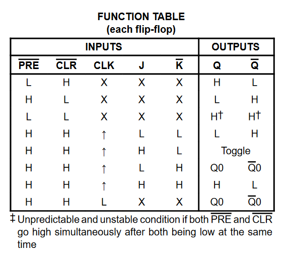
So you can indeed use the !PRE and !CLR lines on a JK Flip-Flop such as the 74ACT109 that has those lines. No need for a clock to be present, although you will want to tie the clock line low. As seen in the truth table from the datasheet:

74109_truth_table

See how the CLK line is a "don't-care" if either !PRE or !CLR are active (low). And so long as the CLK is low when they both return to HIGH then the outputs will retain their previous state.

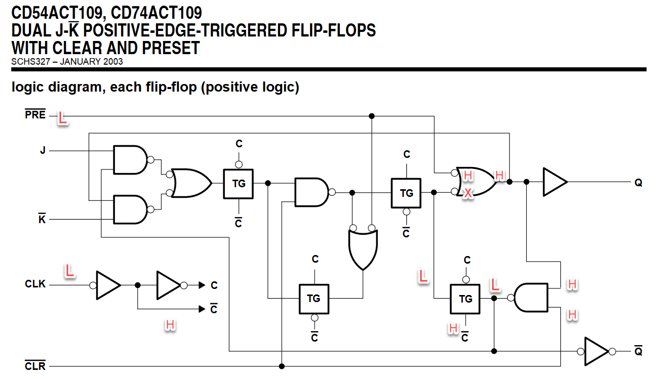
If you want even more warm-fuzzies take a look at the actual logic-diagram: 7x10⁹_logic_diagram

Here I've activated the !PRE line by bringing it LOW and you can see it propagates through the logic to hold the value.

It's essential an SR latch, it's just easier to get buy a JK FLIP-FLOP with set and reset than it is to buy just an SR latch.

And finally these chips are like $0.20 so definitely buy one and bread-board it up.

\$\endgroup\$

Your Answer

By clicking “Post Your Answer”, you agree to our terms of service and acknowledge you have read our privacy policy.

Not the answer you're looking for? Browse other questions tagged or ask your own question.