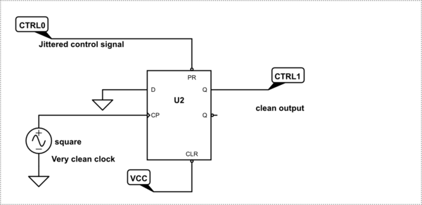
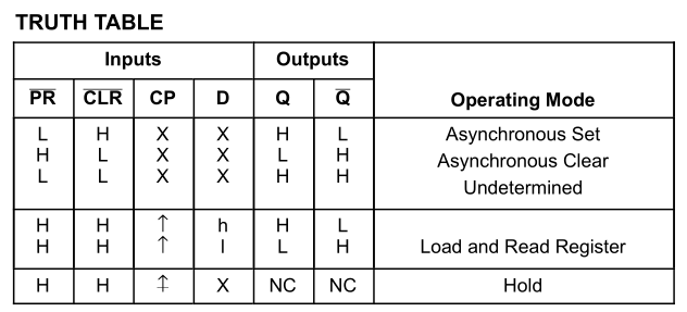
We call a clocked event synchronous and Preset ( or set) or Clear (or Reset) as asynchronous events.
Your cct gives an asynchronous Preset and only when released ( going high) allows CP to transfer D to Q and thus reset the "1" to a "0" giving a +ve pulse with only synchronous trailing edge.
So it only cleans up the negative edge in your case. The prefered way is to use D input and then both edges are synchronous. But this relies on your input D being longer in any state than the period between clock pulses.
i.e. a much slower square wave clock.
Also PR and CLR are both "negative logic" meaning active low. Some CMOS FF chips are "positive logic" for Set and Reset for various reasons not relevant now.
Better example
Let me describe a personal technical experience circa late 77 that will illustrate this better ( just came to me).
Say you have designed a synchronous telemtry system (SCADA) and you have some unused bits available every 1/24th of an 8kHz frame or 3kbit in a 1.544Mbps data stream. The problem is I need two 1kHz channels of analog bandwidth to send a VCO that tracks two servo motor currents to get instant feedback on load friction. So I decide to use a VCO to sense amplified motor current from 0 to 1kHz per motor and send the pulse in a 3kHz data stream as a 1 or 0 then like a Tach reconstruct the analog current voltage and sent to a panel meter. 3 samples per Hz , no problem except it shows problems of aliasing because I just sampled the VCO to send on the data stream and I forgot momentarily that Shannon's law means this sampled data has harmonics and as a result I get alaising the difference frequency of those harmonics.
So how do you get rid of harmonics in this case of a square wave from a sampled VCO in a data stream? if I used a 1 shot with a period greater than the 3KHz bit stream, I was sending the bit ocassionaly twice in this synchronous sampled VCO. If I make it narrower I might miss it which is just as bad. But if I PRESET the D FF with the VCO at 1kHZ max with an RC differentiated edge from the VCO and then only once that bit is sent synchronously reset it by using my 3KHz clock with D=0 then that bit is transmitted only once and I won't get any aliasing effects. ( delta f)
Bingo it works and I can take it all the way up to 3kHz VCO and send it in the 3kHz sample misc. maintenance frame byte. But I decide to send two sub-channels of 1kHz VCO's for 2 motor currents and use the 3 subchannel of 1kHz BW for something else. That was 1 day problem and solution to bench test then write a rework instruction for my NASA-qualified soldering female tech with marked pink prototoype drawings. (meaning no ECN required)
It just came to me this morning that I used the same circuit above with a 1us PRESET edge pulse and the synchronous sub-frame clock to clock "0" into D to reset the synchronous VCO register. So with this method, you really only need 1 sample rate per Hz of BW input and not two as in analog Shannow's Law. but in reality Shannow's law still applies. Can you guess why?
Does this answer make good sense? Does my example help make it important? ??


