0
\$\begingroup\$

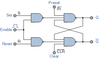
For example let us consider an SR flip flop.

If the clear input is 0 (active low) and preset is 1 this will force the output to go to reset condition (Q=0 and Q'=1.) But if the clear=0 and Preset =1 in this state we give set=1, reset=0 and clock =1 then will both the output be 1 and 1?

If so then using the overriding input when clock =1 is a problem. How to deal with this problem?

SR flip flop

\$\endgroup\$
6
  • \$\begingroup\$ Q'=1 (that was a typo) and Q can be either 1 or 0 so if both outputs are 1 then that causes a problem.How to get rid of this problem as one should be the compliment of the another \$\endgroup\$
    – user257480
    Commented Jul 12, 2020 at 16:40
  • \$\begingroup\$ It's not a 'problem', it's the behaviour of that circuit. If you don't want that behaviour, then either avoid those input conditions, or use a different circuit with a different behaviour. Perhaps use a circuit with an inverter on the Q output to give the Qbar output. That would guarrantee that Q and Qbar are always complements, except for the few nS of the inverter propagation delay. \$\endgroup\$
    – Neil_UK
    Commented Jul 12, 2020 at 16:55
  • \$\begingroup\$ So if the clear input is pressed regardless of the input of the S and R the output will be Q'=1 and Q=0 is false? \$\endgroup\$
    – user257480
    Commented Jul 12, 2020 at 17:18
  • \$\begingroup\$ PRE is kept at 1 \$\endgroup\$
    – user257480
    Commented Jul 12, 2020 at 18:48
  • \$\begingroup\$ please review the NAND gate .... you would not be asking the question in your comment if the operation of the NAND gate was clear in your head \$\endgroup\$
    – jsotola
    Commented Jul 12, 2020 at 20:05

2 Answers 2

1
\$\begingroup\$

There are several ways to deal with this. You could, for example, ignore the \$\overline{Q}\$ output and use only the \$Q\$ output. If you really need the complement then add an inverter.

You could also design the logic around the latch to eliminate the possibility that the asynchronous inputs could be asserted while the enable is also asserted. A better idea might be to prevent the enable from being asserted while either of the asynchronous inputs is asserted. The best approach depends entirely on how you intend to use the latch, and which inputs you want to be prioritized over the others.

By the way, the circuit you present is not an edge-sensitive circuit, it is a level-sensitive circuit. That's why it has an \$enable\$ input rather than an actual \$clock\$ input. I think most of us here would call that a latch rather than a flip-flop.

\$\endgroup\$
10
  • \$\begingroup\$ the problem remains regardless of the input being enable/ pulse transition detector to detect an edge. \$\endgroup\$
    – user257480
    Commented Jul 12, 2020 at 17:03
  • \$\begingroup\$ So if the clear input is pressed regardless of the input of the S and R the output will be Q'=1 and Q=0 is false? \$\endgroup\$
    – user257480
    Commented Jul 12, 2020 at 17:05
  • \$\begingroup\$ Look at it this way: If CLR is low then Q' must be high, regardless of any other inputs. If PR is low then Q must be high, regardless of any other inputs. So your last statement "clear input is pressed regardless of...S and R..." can not be answered without specifying the value of PR. You really need to make a truth table. \$\endgroup\$ Commented Jul 12, 2020 at 18:37
  • \$\begingroup\$ PRE is set to 1 which is always done as both PRE and CLR can't be 0 at the same time \$\endgroup\$
    – user257480
    Commented Jul 12, 2020 at 18:43
  • \$\begingroup\$ if i update it , if the clear input is pressed(0 active low) and preset is kept 1 regardless of the input of the S and R the output will be Q'=1 and Q=0 is false? \$\endgroup\$
    – user257480
    Commented Jul 12, 2020 at 18:45
-1
\$\begingroup\$

First of all we have to know about little bit about latches after we going to flipflop.. Basically they are such as: SR, RS JK D T-flipflops

Simple in SR --flipflop first we have to see what components we used in f/f. Basically 4 nand gates with combination of latches with clock pulse is constant with 1. Now we have to check by some methods. Basically. Is drawback of SR-F/F. We basically change clk pulse.. But only we deal to overcome with this situation by using JK-Flipflop..

\$\endgroup\$
6
  • 1
    \$\begingroup\$ this has nothing to do with my question \$\endgroup\$
    – user257480
    Commented Jul 12, 2020 at 18:51
  • \$\begingroup\$ In SR F/F both Q and Qnot are not same... \$\endgroup\$
    – Ankit
    Commented Jul 12, 2020 at 18:56
  • \$\begingroup\$ No, it is not true that Q and Q' can not be the same, not for the simple cross-coupled NAND or NOR latch. \$\endgroup\$ Commented Jul 12, 2020 at 18:58
  • \$\begingroup\$ Yes that is the drawback of SR F/F \$\endgroup\$
    – Ankit
    Commented Jul 12, 2020 at 19:01
  • \$\begingroup\$ Overcome by JK f/f \$\endgroup\$
    – Ankit
    Commented Jul 12, 2020 at 19:01

Your Answer

By clicking “Post Your Answer”, you agree to our terms of service and acknowledge you have read our privacy policy.