4
\$\begingroup\$

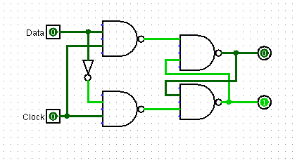
I am trying to create a D Flip Flop to use in a bidirectional 4-bit shift register, using Logisim. However, when using my D flip flop the shift register acts just as a normal register setting the bit for all 4 D flip-flops outputs instead of one by one. It works properly when using the D flip-flop provided by Logisim but I am wondering how to achieve this using my own D Flip-Flop.

This is the design of my D Flip Flop This is the design of my D Flip Flop
And this is the shift register (with the boxes representing the D Flip Flop) enter image description here
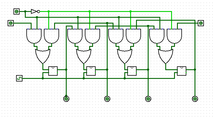
Any help would be greatly appreciated

\$\endgroup\$
3
  • 2
    \$\begingroup\$ This is a latch, not a flip-flop. The output will keep following the input as long as the clock is high. A flip-flop will not do that. \$\endgroup\$ Commented Nov 18, 2020 at 17:14
  • \$\begingroup\$ Unfortunately, there was no way to pass the clock output straight into the subcircuit so the latch was a workaround. \$\endgroup\$
    – lilnut
    Commented Nov 18, 2020 at 17:40
  • \$\begingroup\$ what...........? \$\endgroup\$ Commented Nov 18, 2020 at 17:51

2 Answers 2

5
\$\begingroup\$

D flip-flop provided by Logisim which you used for simulation was a positive edge-triggered D Flip-Flop. While what you have designed is a level-sensitive D latch.

You have to cascade two of those D latches in master-slave configuration to obtain a positive edge-triggered D Flip-Flop.

reference: Flip-Flops Wikipedia

\$\endgroup\$
1
  • \$\begingroup\$ For a rising-edge detector you can use the same configuration as the upper diagram, but put the not-gate on the other enable-pin. \$\endgroup\$
    – Rd Basha
    Commented Oct 25, 2022 at 18:12
1
\$\begingroup\$

Shorten your clock pulse so that it is gone by the time the output data from one flip flop reaches the D input of the next. At the moment, with a long clock high time, when the new data arrives at a D input it is transferred straight through the flip flop and on to the next because the clock is still high.

This is a technique for producing a very short clock pulse, the duration of which is shorter than the time taken for the data to transition through the stage.

D type flip flop

\$\endgroup\$
3
  • 1
    \$\begingroup\$ Unfortunately, even of you set the clock to Ton to 1 tick and Toff to 31 ticks, it still doesn't work. I suspect it calculates differently the states for the builtin D flip flop. \$\endgroup\$ Commented Nov 18, 2020 at 16:59
  • 1
    \$\begingroup\$ @aconcernedcitizen yes, latches are different from flipflops. \$\endgroup\$ Commented Nov 18, 2020 at 17:14
  • \$\begingroup\$ @user253751 True, but in real life you might get away with the inherent delays (also why you posted your answer). One of the reasons why I called it "concoction". \$\endgroup\$ Commented Nov 18, 2020 at 19:59

Your Answer

By clicking “Post Your Answer”, you agree to our terms of service and acknowledge you have read our privacy policy.

Not the answer you're looking for? Browse other questions tagged or ask your own question.