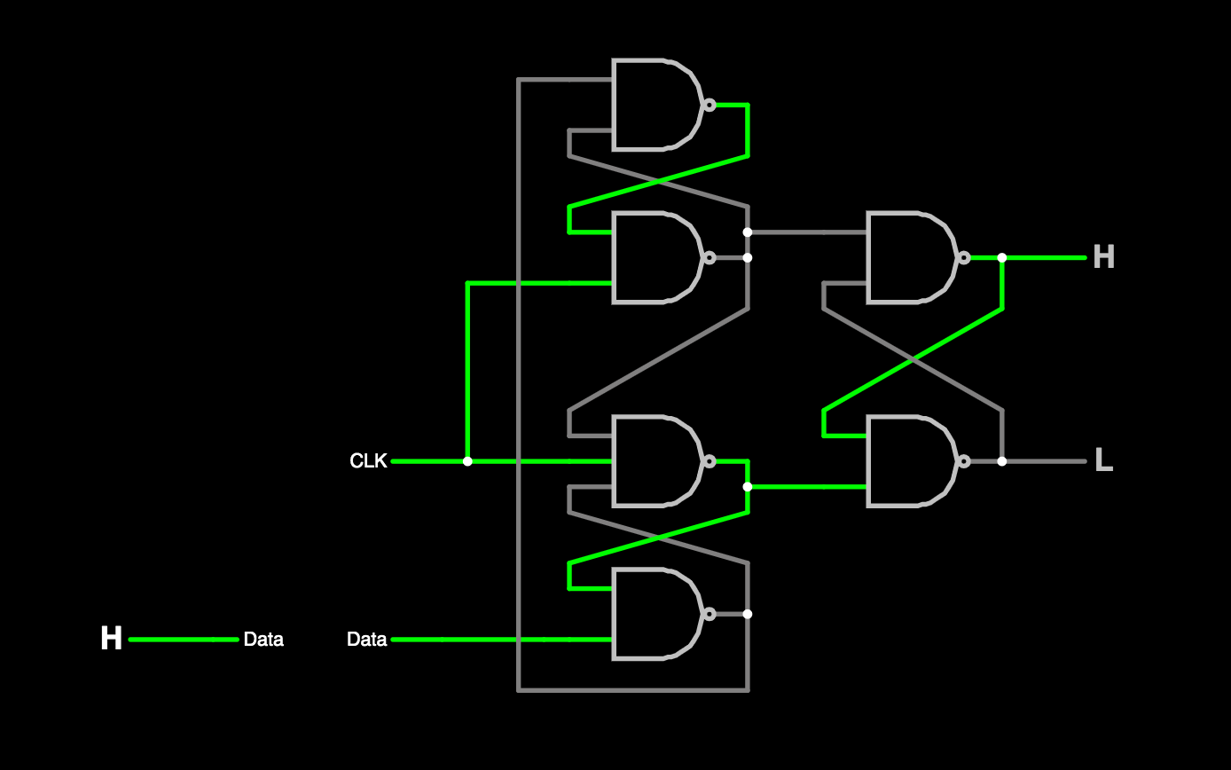
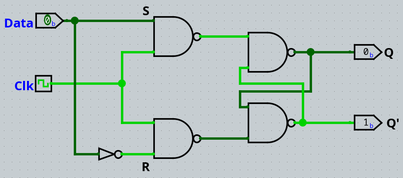
I have the following D flip-flop circuit:
I would call it a D latch. I would call a circuit a flip-flop if it is edge triggered rather than level triggered. However, your circuit is not edge triggered. It is level triggered.
it seemed that the circuit was actually level-triggered, since when I ... change[d] the value of Data while the clock was on high (but past the positive edge), the values of Q and Q' would still update.
That is correct. It is level "triggered". The "clock" in your circuit is really an "enable".
What I don't understand however, is what actually makes flip-flops positive/negative edge triggered.
There are two (possibly more) ways to make a circuit edge triggered, rather than level triggered.
One way is to create (from the clock input) a very short pulse on a rising (or falling) edge of the clock. This can be done by making a delayed version of the clock (often an inverted as well as delayed) and recombining it with the original clock input. For example:

simulate this circuit – Schematic created using CircuitLab
Assuming the logical inverter has sufficient delay, when the input goes high, the output will go temporarily high. However, as soon as the output of the inverter goes low, the output will go low. Some variation of this circuit can be used to limit the "window" in which a change in the data input can result in a change in the output of a flip-flop.
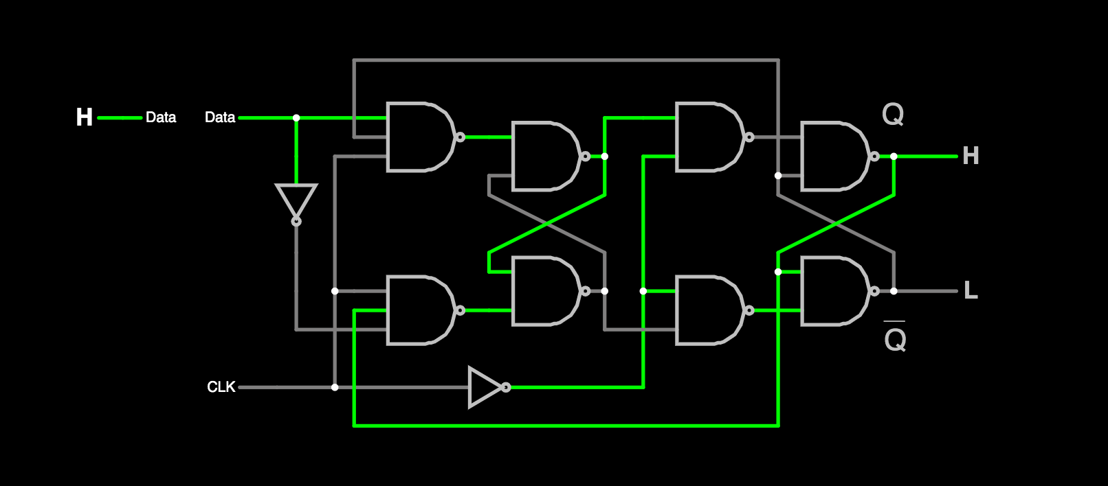
A second approach to making an edge triggered flip-flop is to use feedback in such a way that when the clock pulse arrives at the flip-flop, the data is latched, and then the internal state of the flip-flop quickly moves to a stable state in which data inputs have no effect. Flip-flops designed along these lines include circuits like this:

You may simulate this circuit interactively using this Falstad link
You will notice that in this circuit, there are actually 3 latches. And there is feedback into the 2 latches on the left hand side of the schematic. This feedback is used to "move" these latches into states where they are impervious to future input changes. Only when the clock becomes inactive again, do these latches regain the ability to respond to input changes.
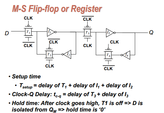
Although it uses feedback, and thus might be subsumed under the 2nd method mentioned above, the typical master-slave flip-flop is worth mention on its own. It does use feedback as shown in this schematic:

This circuit can be simulated here.
Unlike a transparent edge triggered flip-flop, the master-slave flip-flop delays the appearance of the input for a half-cycle of the clock. That is, there are two phases involved in moving the input to the output. Phase 1 latches the input, phase 2 moves the input to the output latch.


