2
\$\begingroup\$

I'm confused when seeing wires contain GND and VCC in a schematic. Mainly their flows.

I never confused when see in digital logic wires schematic like logic gates. I understand flows in digital schema.

Meanwhile i don't understand how flows in electronic schemes due to there's two flows like conventional flow (VCC to GND) and electron flow (GND to VCC) that's will be problem for me about its state.

So, do u think contain or much electrons in a wire means 0 or 1 state? Or there's no relation?

I know HIGH voltage means 1 which it's VCC and LOW voltage means 0 which it's GND. But, Aren't unconnected wires means 0 state too? Because it contains 0 volt in wires. But also it's not work in some devices when disconnect wires to express 0 state.

The problem is when i want identify, analyzing, and solving digital logic in wires.

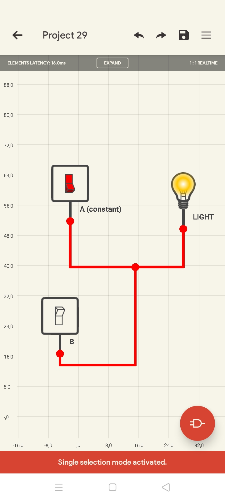
Like this picture below,1 state in red color, black means 0. But theres no blacked wires on below. consider input A is constant 1. Then the output (LIGHT) is always 1. In same wires, input B is variable, but there's no way to turn off the light (make output 0 state) because when B=0 the output still 1. It's because A+B = 1+0 = 1 And moreover, if B=1 then A+B = 1+1 = 1

This digital scheme truth table same as OR gate. But im talking about directly connected wires. Which will it affect to other wires or not in digital electronic scheme which contain VCC and GND.1
\$\endgroup\$
3
  • 6
    \$\begingroup\$ When looking at a schematic, forget about electron flow. You should always be thinking in terms of conventional current flow. \$\endgroup\$
    – user57037
    Commented Dec 9, 2020 at 6:46
  • 4
    \$\begingroup\$ Please note that a voltage is always the difference between two levels of electrical potential. An open wire does not have a zero voltage, it can have any voltage. But as soon as you try to measure it in the real world, you are shunting it with the measuring device that is some kind of impedance. In almost all cases this will discharge any potential from the open wire, resulting in a difference of zero. \$\endgroup\$ Commented Dec 9, 2020 at 8:23
  • 1
    \$\begingroup\$ You said "I know HIGH voltage means 1 which it's VCC and LOW voltage means 0 which it's GND." That is not necessarily true. You could have current-mode logic or a differential pair where the difference between two wires is your signal. And there was a standard logic family called ECL which apparently used 0 and -5 volts (it's based on current, not voltage). \$\endgroup\$
    – Matt
    Commented Dec 9, 2020 at 22:52

6 Answers 6

12
\$\begingroup\$

In digital logic circuits, 1 and 0 are labels, not physical things. Current and voltage are physical things. For common logic circuit like TTL and its many derivatives, a voltge in the range of 0 v to +0.8 V is called a logic 0, and a voltage in the range of 2.4 V to 5 V is called a logic 1.

In general electronic circuit discussions, electron flow rarely comes up. Circuit power is discussed in conventional flow - current flows from + to -, from a more positive voltage to a more negative (or less positive) voltage.

Your diagram is ok for showing where energy might move from and to, but it is not a schematic. A schematic will have a line (or line structure, like a bus) for every individual conductor, showing return paths for all currents.

\$\endgroup\$
4
\$\begingroup\$

All logic is based on assumptions of the analog parameters. You are trying to reason the logic of an AC lighting circuit to DC logic. So what are your assumptions?

  • The input voltage is nominal within accepted tolerances.
  • The load is nominal and functional
  • you know the ganged switch appears to be an OR gate with 2 switches
  • you assumed the switch is connected to the same Vac source and the same AC light bulb load and thus the load draws the same current expected if either or both switches are on.
  • you know the bulb is resistive and there are thermal effects on resistance but it draws current according to its power rating.
  • you know the current is in phase with Vac since it is a resistive load so both polarities are in sync.

These are all Analog parameters, the only digital parameter is if these assumptions are true and there is no faulty bulb or wiring, then ON=1 and OFF=0

The same is true for DC logic with a few pages of Analog parameters.

  • TTL Logic = 1 if the input is floating due to internal bias, but a Pullup of 10K is recommended for noise immunity from a long wire if connected to it.
  • CMOS logic is charge voltage controlled and draws far less than 1uA and so the input could be any state floating so a driver load or a resistor must define its input voltage level and thus its logic state.

In both cases, we call the middle range illegal meaning if the voltage is not between the input low and high levels called Vil(max) and Vih(min) levels it's not guaranteed to be a valid logical level as the noise could make it unreliable just as if a loose wire on the AC bulb causes excessive resistance gets hot and drops the voltage when it is supposed to be at rated V. Both would be a fault condition. Yet the transition time between levels is well defined.

  • you know that current flows out or down from a positive DC voltage by conventional wisdom which is actually opposite to the flow of electrons.

So stop thinking about electrons in logic diagrams.

All logic is just a predefined set of voltage rules which are guaranteed with known currents driver currents vs Vout and thus Rout=Vo/Io which changes for each logic family. but the voltage levels are compatible. There are over 50 different series of logic which if they are compatible on the same supply, the differences may be power efficiency, speed and output impedance. Vo/Io (max)

  • Thus we always learn the analog values to understand the rules, and these internal comparator-like functions by design determine its logic value 0 or 1.

  • normally CMOS threshold is Vdd/2 +/-25% over temperature extremes for some OEM's , whereas Schmitt Trigger gates and inverters have hysteresis to improve noise immunity.

  • normally TTL logic including RS232 has an input voltage threshold of 2 Vbe diode drops = 1.3V for all types of TTL and CMOS 74HCT' family.

Once you understand the rules of analog logic, the logic is easier to understand.

p.s. All Schematics are just Logic Diagrams and say nothing about the analog characteristics or layout or wiring, unless you specify that in the notes for supply decoupling caps and tolerances and Part numbers or family series.

\$\endgroup\$
4
\$\begingroup\$

There is another state you may not have been introduced to. It is called a high impedance state or Z.

Imagine a logic device connected to a bus. The bus may always have a logic high or logic low in it. Now this causes a problem, what if that particular device is not being used, then how do you "disconnect" it from the bus because a logic low does not always mean no signal but actually means the opposite.

In this case you use what is called a bi-directional buffer 74LS245. It has three states. High, Low and high impedance.

As the name suggests the voltage drop across the high impedance circuit tends to zero. Thereby effectively "disconnecting" that particular logic device.

\$\endgroup\$
4
\$\begingroup\$

Flow is always "conventional flow" from VCC to GND. Don't worry about electrons when you are looking at a schematic.

VCC is 1, GND is 0, and an input pin that is not connected is in an UNDEFINED STATE. Neither high nor low, neither 1 nor 0. It is a design error to leave an input pin with no driving source. The behavior of the circuit may change randomly if an input is not connected.

An input which is not needed can be pulled up to VCC or down to GND with a resistor. Check the datasheet to see if it has recommendations for unused inputs.

Some inputs may have internal pullups (or pulldowns) inside the IC. If so, it may be OK to have no external connection. But it is worth checking the datasheet to make sure.

\$\endgroup\$
3
\$\begingroup\$

Current flow from positive to negative is called convenional current. This was settled upon (notably, by Ben Franklin) before electron theory was understood. This notation is used in schematics and electronics measurement gear.

We now know that electrons flow from negative to positive charge (that is, electrons have negative charge.) So when we talk about semiconductors or vacuum tubes, (that is, electron theory) we switch gears and talk about electron flow, recognizing the underlying physics of electricity.

Nevertheless, the math works out the same when analyzing circuits.

In logic we can use just about any notation we want to indicate ‘true’ or ‘false’. Again, most of the time we settle on VDD as ‘true’ and GND as ‘false’ for convenience, yet it’s also valid to call a signal ‘low-true’ and have an inverted polarity. Older logic families like TTL in fact worked better when using low-true definitions for signals. This low-true preference persists in some interfaces like DRAM controls, even though modern CMOS logic doesn’t care.

It’s also possible to define logic as the presence or absence of power, like your light bulb example. ‘True’ would be energized, ‘false’ would be de-energized. There are early electromechanical computers that worked this way, using relays and switches for logic elements.

Big picture: logic is logic, and can be represented in many ways: electronically, electrically, or even mechanically. As long as you have states to map logic variables you have a way of representing ‘true’ and ‘false’.

And I get the even larger point that there is somewhat of a cultural bias in the meaning of ‘positive’ and ‘negative’, and it is indeed arbitrary.

\$\endgroup\$
3
\$\begingroup\$

A practical tip: If you see only the one end of a wire (rail) and you want to check if it is GROUND, it is not enough to connect a voltmeter between it and ground because it will show 0 V in both cases - GROUND and unconnected (floating).

You need to connect a (pull-up) resistor between Vcc and the wire. If its voltage remains 0 V, it is GROUND; if the voltage becomes Vcc, it is unconnected (floating).

These considerations are also valid for the circuits with high impedance state. If you connect a voltmeter to the circuit output and it shows 0 V, you do not know if this is 0 state or high impedance state.

The same considerations are valid for the so-called "open collector".

\$\endgroup\$

Your Answer

By clicking “Post Your Answer”, you agree to our terms of service and acknowledge you have read our privacy policy.

Not the answer you're looking for? Browse other questions tagged or ask your own question.