Searching "hls axi dma" on this site gives a few related issues but none of which I can use to fully deduct a solution for my problem.
My code generates "random" output on IO1 and reads input on IO4. To test my code, I short IO1 and IO4 and, I keep reading IO4, and whenever there is a signal in, I read what was on the output IO1. Ideally whenever IO4 has signal in, IO1 should also read signal out. I tested it this way to see whether I was off by one and needed adjustements to code or if everything was working as intended.
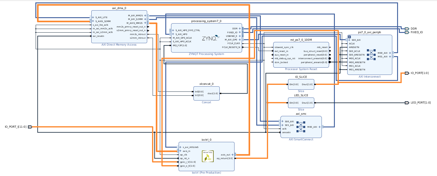
This is my block design
And here is the code
typedef ap_axis<8,1,1,1> stream_type;
static ap_uint<32> lfsr = 51763;


ap_uint<4> ioctrl(bool run, hls::stream<stream_type> axis_in, hls::stream<stream_type> axis_out, ap_uint<14> &usr_gpio, volatile ap_uint<12> gpio_i, volatile ap_uint<2> gpio_o) {
#pragma HLS INTERFACE ap_ctrl_none port=return
#pragma HLS INTERFACE s_axilite port=run
#pragma HLS INTERFACE s_axilite port=usr_gpio
#pragma HLS INTERFACE axis port=axis_in
#pragma HLS INTERFACE axis port=axis_out
#pragma HLS INTERFACE ap_none port=gpio_o
#pragma HLS INTERFACE ap_none port=gpio_i

    ap_uint<4> state = 0;


    if (run) {
        usr_gpio = (ap_uint<14>) gpio_i + ((ap_uint<14>) gpio_o << 12); // This was used for reading before AXI implementation

        bool b_32 = (lfsr & (1<<31)) >> 31;
        bool b_22 = lfsr & (1<<21) >> 21;
        bool b_2 = (lfsr & (1<<1)) >> 1;
        bool b_1 = (lfsr & (1<<0));

        bool new_bit = b_32 ^ b_22 ^ b_2 ^ b_1;
        lfsr = lfsr >> 1;
        lfsr = lfsr | (new_bit << 31);

        state = (ap_uint<4>) (lfsr.to_uint() & 1);

        if (state == 1) {
            state = 5; // 0101 = [IO 0, LED 0]
        } else if (state == 0) {
            state = 10; // 1010 = [IO 1, LED 1]
        }

        // AXI
        stream_type val_in = axis_in.read();
        stream_type val_out;

        // Here I check whether gpio input is detected
        ap_uint<14> bit_hit = (ap_uint<14>) gpio_i & (ap_uint<14>) 0x02;
        if (bit_hit == 0) {
            // I read gpio output and generate a val_out.data (should ideally always be 0x3)
            ap_uint<8> out_bit = (ap_uint<8>) gpio_o & (ap_uint<8>) 0x01;
            val_out.data = (1<<1) | out_bit;
        } else {
            // If nothing detected, set 0
            val_out.data = 0;
        }

        // As a slave to tutorials, I just copy over everything I don't understand.
        val_out.keep = val_in.keep;
        val_out.strb = val_in.strb;
        val_out.user = val_in.user;
        val_out.last = val_in.last;
        val_out.id = val_in.id;
        val_out.dest = val_in.dest;

        axis_out.write(val_out);

    } else {
        usr_gpio = 0;
    }

    // Set output
    return state;

}
Now, I allocate streams on PS, send and empty allocated stream to PL, which will initiate the output stream from PL, and I read output buffer on PS. These are some of values of the AXI stream I read from PS: [0, 0, 0, 2, 2, 0, 3, 2, 2, 0, 0, 3, ...]
The 0's are fine I though, and the 3's. But what the hell are the 2's. 2 = b'10', that means I hit this line
val_out.data = (1<<1) | out_bit;
But how can gpio input be detected without anything being outputted. Furthermore, bitstream is generated at 100MHz clock. If setting the clock to 250MHz (in PS from pynq.clocks), there are more 3's in the stream to PS, while setting lower frequencies.. say 25MHz, all 3's are gone and only 0's and 2's are read.
Theories:
- I have misunderstand FPGA's chronological execution and this alignment is completely random!?
- I should not set TLAST on every cycle, only when stream in buffer is finished. !?
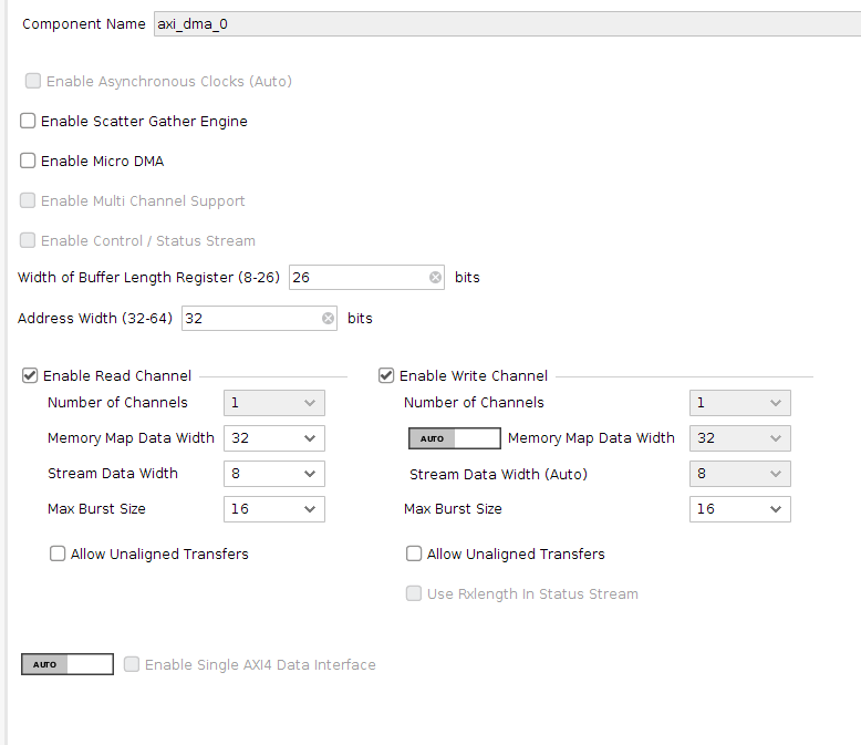
Appendix :slight_smile: This my AXI DMA setup


