1
\$\begingroup\$

I have read (and been told) numerous times that for a shift register, the clock should run reversely to the data (e.g. http://www.edaboard.com/thread103493.html).

Main Question: Is this definitely also true for Ring Counters (or LSFRs)?

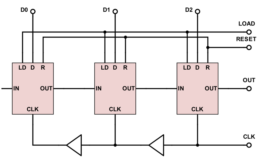
I am building a block like this, where the output is again connected to the input ("ring counter"):

enter image description here

Each square consists of a D flip flop and a 2-1 MUX which initializes the register from D when LOAD is high. This is just a tiny example, in reality it will be between 20 and 30 registers.

Now I am facing unexpected problems which I think are due to hold time violations. I nailed down one problem when initializing the register with "11000...1". In the first cycle, all data is consistent. However, in the second cycle, the content is "01100....0" instead of "111000...0". The clock of the last register is the fastest, so it switches from 1 to zero first (which is the output and also input to the first register). However, the clock of the first register is much delayed and hence stores the new value 0 rather than the old one, 1.

So I doubt that this rule applies to ring counters/LFSR. If this is the case, what is the correct way to implement a ring counter to minimize hold time violation issues?

\$\endgroup\$

1 Answer 1

0
\$\begingroup\$

There are two ways to do this and a lot depends on the technology of the D types. When the D type has a significant hold time then you need to run the clock as you have shown and making ring counters or other circular shift registers will be impossible unless you add an extra flop or latch at the high end of the register to temporarily store the top or end bit until the clock reaches the other end.

Even with this you are faced with a race condition of clock propagation against the last D flop propagation delay+first flop setup time.

Most technologies today have a low or zero hold time requirement. In this case you can concentrate on getting the clock to the all flops at the same time using a "clock tree". In this you drive multiple flops from one buffer, if you cant drive all the flops from one buffer you use multiple buffers and balance the fan out of each in an attempt to keep propagation times the same.

\$\endgroup\$
2
  • \$\begingroup\$ Great! I had the clock tree first but then I was told I should run the clock opposite of the data and I ran into problems. Before I confirm your answer as solution, to make sure: Running the clock backwards to data is true for shift registers but NOT when there are loops (LSFR, ring counter)? \$\endgroup\$
    – divB
    Commented Feb 20, 2017 at 20:48
  • \$\begingroup\$ Usually it is tech dependent my experience is with ASIC and there we always use clock trees. If there are hold time violations the tools put in buffers between stages to slow things down a bit. To reiterate if your flops have low or zero hold time use a clock tree. \$\endgroup\$
    – RoyC
    Commented Feb 20, 2017 at 20:53

Your Answer

By clicking “Post Your Answer”, you agree to our terms of service and acknowledge you have read our privacy policy.

Not the answer you're looking for? Browse other questions tagged or ask your own question.