0
\$\begingroup\$

I came across an interesting yet challenging problem of finding the frequency of a series of pulses. The pulses can have a frequency anywhere from 1 to more than 100 Hz. The goal is to detect if the pulses have a frequency between 3 and 60 Hz. That is, raise a flag or light up an led if the frequency falls between 3 and 60 Hz. The constraints are -

  1. Using microcontrollers are not allowed
  2. Using a frequency-to-voltage converter IC is not allowed.
  3. False positives are allowed but false negatives are not allowed.
  4. (weak) The pulses can have a duty cycle less than or more than 50%, not necessarily equal to 50%.

Can you please suggest a method of doing so?

One method that I have designed and analysed is to use a counter IC and count the number of pulses, and reset the counter every 1 second (using a separate timing circuit like 555 timer). If the output number of pulses is between 3 and 60 (one can use a logic circuit to determine that) then raise the flag. The logic circuit required for this would be a bit tedious, and depends on the type of output of the counter IC.

\$\endgroup\$
7
  • 4
    \$\begingroup\$ Why such restrictions? Is this a homework exercise? \$\endgroup\$ Commented Nov 2, 2019 at 13:26
  • \$\begingroup\$ @TomCarpenter it is a project that I'm working on and the restrictions are there because they are fabricated. I may not be answering your question properly but the first two restrictions are there because I can already solve it using them. I just want a different and more basic method. One that uses the least resources. The other two are just inherent restrictions of the problem. \$\endgroup\$
    – shysd
    Commented Nov 2, 2019 at 13:42
  • 1
    \$\begingroup\$ So, the real problem that I foresee: we propose a sensible solution, you agree it's sensible, but reject it, because you already knew that. Then we'll have wasted time. For example, the thing I'd recommend is using an FPGA to build a small debouncer + counter + state machine to detect the pulse frequency, just as you would have done in a microcontroller. In fact, I'd actually have recommended to implement a mini CPU inside the FPGA (think picorv32), because you seem to be trying to weigh likelihoods (like misdetections / false positives). Then you'd basically have built a microcontroller. \$\endgroup\$ Commented Nov 2, 2019 at 13:46
  • 2
    \$\begingroup\$ So, you come here for the most sensible solution, but preclude the most sensible solution – not a very promising start; it means that all solutions we'd suggest kind of are "equally bad", and of bad solutions there's just too many. \$\endgroup\$ Commented Nov 2, 2019 at 13:47
  • \$\begingroup\$ @MarcusMüller I agree. I have posted this question to initiate discussion on the problem. It is not about the solution being "sensible" or "bad", I never commented on that. That is why I put them as 'restrictions'. I apologize if I was not clear earlier, but the goal here is to find a solution that just respects the restrictions, it may be good or bad it doesn't matter. I even posted on of my takes on the problem but never commented on the good/bad-ness of it. \$\endgroup\$
    – shysd
    Commented Nov 2, 2019 at 13:52

1 Answer 1

5
\$\begingroup\$

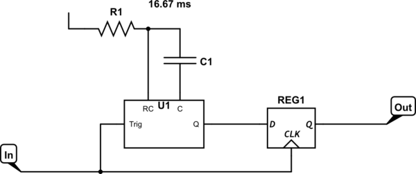
Here's a hint: An edge-triggered retriggerable monostable multivibrator followed by a DFF makes a very effective frequency discriminator.1

schematic

simulate this circuit – Schematic created using CircuitLab

U1 is the one-shot. Its Q output goes high for 16.67 ms every time there's a rising edge on the input. If the output is still high when the next edge comes along, then the period must be less than 16.67 ms, which means that the frequency is greater than 60 Hz. The DFF captures this status — its output is continuously high for frequencies greater than 60 Hz and continuously low for frequencies less than that.

Build a second one of these with a period of 333.3 ms, and combine their outputs with a simple gate to produce the result you're looking for. You can build the entire setup on a breadboard with just three chips: a dual one-shot, a dual DFF, and a single 2-input NOR gate.


1 This has applications wherever FSK is used — anything from low-speed data modems for telephones, to data storage on cassette tapes, to early floppy disk drives, among many others.

\$\endgroup\$
2
  • \$\begingroup\$ I'm sorry but I fail to understand how a monostable multivibrator followed by a D flip flop would act such. Won't the time constant of the multivibrator override the pulses thus rendering their frequency unusable? \$\endgroup\$
    – shysd
    Commented Nov 2, 2019 at 15:49
  • \$\begingroup\$ excellent! If you had mentioned something along the lines of 'debounce', I would have got it. For futures readers, the retriggerable monostable multivibrator circuit acts as a 'debounce' circuit in the way that once the first pulse it will ignore any other pulses until it exhausts the time of it time constant (tau = RC), which means the pulse freq is more than 1/RC. \$\endgroup\$
    – shysd
    Commented Nov 5, 2019 at 0:47

Your Answer

By clicking “Post Your Answer”, you agree to our terms of service and acknowledge you have read our privacy policy.

Not the answer you're looking for? Browse other questions tagged or ask your own question.