0
\$\begingroup\$

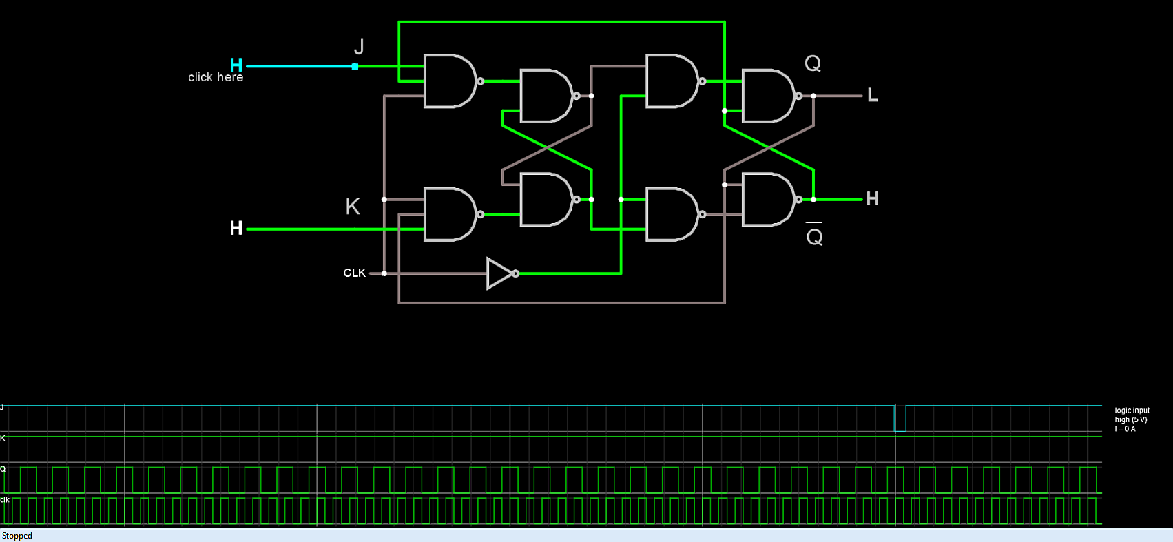
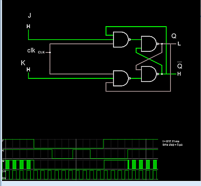
I tried simulating both:

Falling edge triggered one

Regular clocked JK flip flop

I think there is something wrong with them because when both inputs are high they look like they are having a seizure rather than toggling.

I thought I understood it, I've tinkered with it, I've looked at the scopes but at this point I am a bit lost.

\$\endgroup\$

1 Answer 1

1
\$\begingroup\$

You can only make latches this way and bad ones too that oscillate with negative feedback. Notice the blur of oscillations. when both JK =1.

enter image description here

True Flip Flops MUST HAVE 2 latches to make the output edge triggered so that the 2nd stage input conditions cannot change on the clock edge.
enter image description here They are actually implemented in CMOS Transmission gates as well.

\$\endgroup\$
3
  • \$\begingroup\$ But am I not suppose to use something like this when I want to make a falling edge triggered flip flop? sub.allaboutcircuits.com/images/04191.png \$\endgroup\$ Commented Dec 24, 2019 at 2:43
  • \$\begingroup\$ What part of that is an invalid FF do you misunderstand? \$\endgroup\$
    – D.A.S.
    Commented Dec 24, 2019 at 4:24
  • \$\begingroup\$ I believe you. I'm just surprised because I've seen my professor do this and accept projects that were done like this. \$\endgroup\$ Commented Dec 24, 2019 at 5:21

Your Answer

By clicking “Post Your Answer”, you agree to our terms of service and acknowledge you have read our privacy policy.

Not the answer you're looking for? Browse other questions tagged or ask your own question.