2
\$\begingroup\$

The Intel Cyclone IV FPGA supports PCI Express (PCIe) generation 1, and the IO standard for the Tx output is PCML at 1.5 V.

The Cyclone IV Device Handbook volume 2 page 1-13 describes that the Tx output supports 100 Ohm termination. The related figure is this:

enter image description here

I understand that termination is often used at the receiver end to avoid reflections.

Why is there termination at the transmitter end for the PCIe PCML IO standard?

\$\endgroup\$
2
  • 1
    \$\begingroup\$ The PCIE Express specification, physical layer section, should explain that. \$\endgroup\$
    – user16324
    Commented Jan 12, 2021 at 14:36
  • \$\begingroup\$ It's called double termination \$\endgroup\$
    – Mitu Raj
    Commented Aug 28, 2021 at 5:23

2 Answers 2

2
\$\begingroup\$

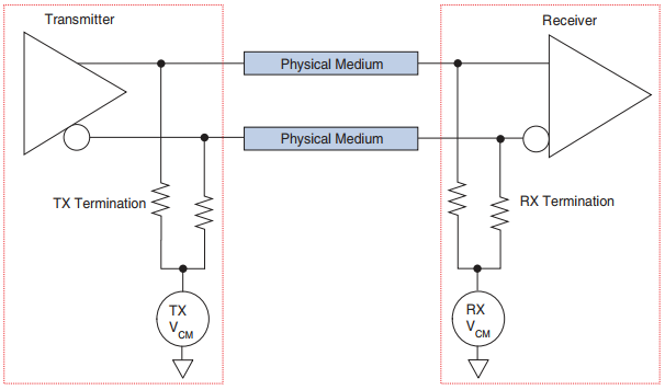
There is termination on the transmitter end due to the same reason, to terminate reflections that arrive back to the transmitter for some reason, and also to drive the 100 ohm transmission line at 100 ohm source impedance, as otherwise the current mode output would have extremely high impedance.

As PCIe lanes are AC coupled, it is also there to bias the current-mode driver output correctly as the output drive current is such that it requires double termination to output correct voltage swings.

\$\endgroup\$
1
  • \$\begingroup\$ Wow... amazing... thanks a lot for the quick and detailed answer :-) \$\endgroup\$
    – EquipDev
    Commented Jan 12, 2021 at 11:02
2
\$\begingroup\$

Justme’s answer is spot-on. The end termination on the other side of the differential pair wires is never perfect so the source termination provides extra attenuation of any reflections sent backwards from the end termination.

There’s one more important thing to note, though. When you terminate both ends of a transmission line, it gains a special property: a single impedance discontinuity in the middle of the line results only in a reduction of amplitude at the receiver, never ringing or overshoot. The idea is that any reflection sent backwards from the impedance discontinuity toward the transmitter dies at the source termination and doesn’t bounce back toward the receiver.

Imagine you wanted to build a system with two boards and a connector in between to pass some PCIe lanes in between. The connector between the boards represents at least a bit of an impedance discontinuity, so the both-ends termination is great here because it lets you go at fast without (as much) fear of the ringing and reflections that would inevitably result from driving a non-both-end terminated line at high speed.

\$\endgroup\$
1
  • \$\begingroup\$ Thanks, very enlightening with details about this interesting method to attenuate reflections from an impedance discontinuity. \$\endgroup\$
    – EquipDev
    Commented Feb 10, 2021 at 18:07

Your Answer

By clicking “Post Your Answer”, you agree to our terms of service and acknowledge you have read our privacy policy.

Not the answer you're looking for? Browse other questions tagged or ask your own question.