0
\$\begingroup\$

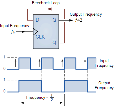
I would like to simulate a simple one-bit counter (or frequency divider) using the D-flip flop.

1-bit counter / frequency divider

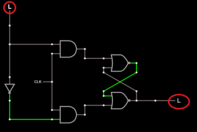
However, I don't want to use the abstracted D-flip flop above. Rather, I want to simulate this using primitive NOR/AND gates directly. I rigged up a D-flip flop based on NOR Gates below.

The full simulation can be seen at this link: http://tinyurl.com/z6mae9c

However, I cannot connect the Q' output back into the "D" input without getting an error (endpoints circled in red below). Can anyone recommend how to fix this? Is this a limitation of the simulation framework? If so, what's a good package to simulate this on?

enter image description here

\$\endgroup\$
1
  • \$\begingroup\$ Button Input is a true voltage source and so is Logic gate out. \$\endgroup\$
    – D.A.S.
    Commented Nov 18, 2016 at 6:41

1 Answer 1

1
\$\begingroup\$

http://tinyurl.com/zonbe7q

It cant work as you expected, but I fixed the simulation

Difference between latch and flip-flop?

\$\endgroup\$
1
  • \$\begingroup\$ Thanks a lot Tony, the link was very helpful! I was able to finally construct a working frequency divider using the master/slave flip flop design: falstad.com/circuit/e-masterslaveff.html \$\endgroup\$ Commented Nov 18, 2016 at 7:47

Your Answer

By clicking “Post Your Answer”, you agree to our terms of service and acknowledge you have read our privacy policy.

Not the answer you're looking for? Browse other questions tagged or ask your own question.