2
\$\begingroup\$

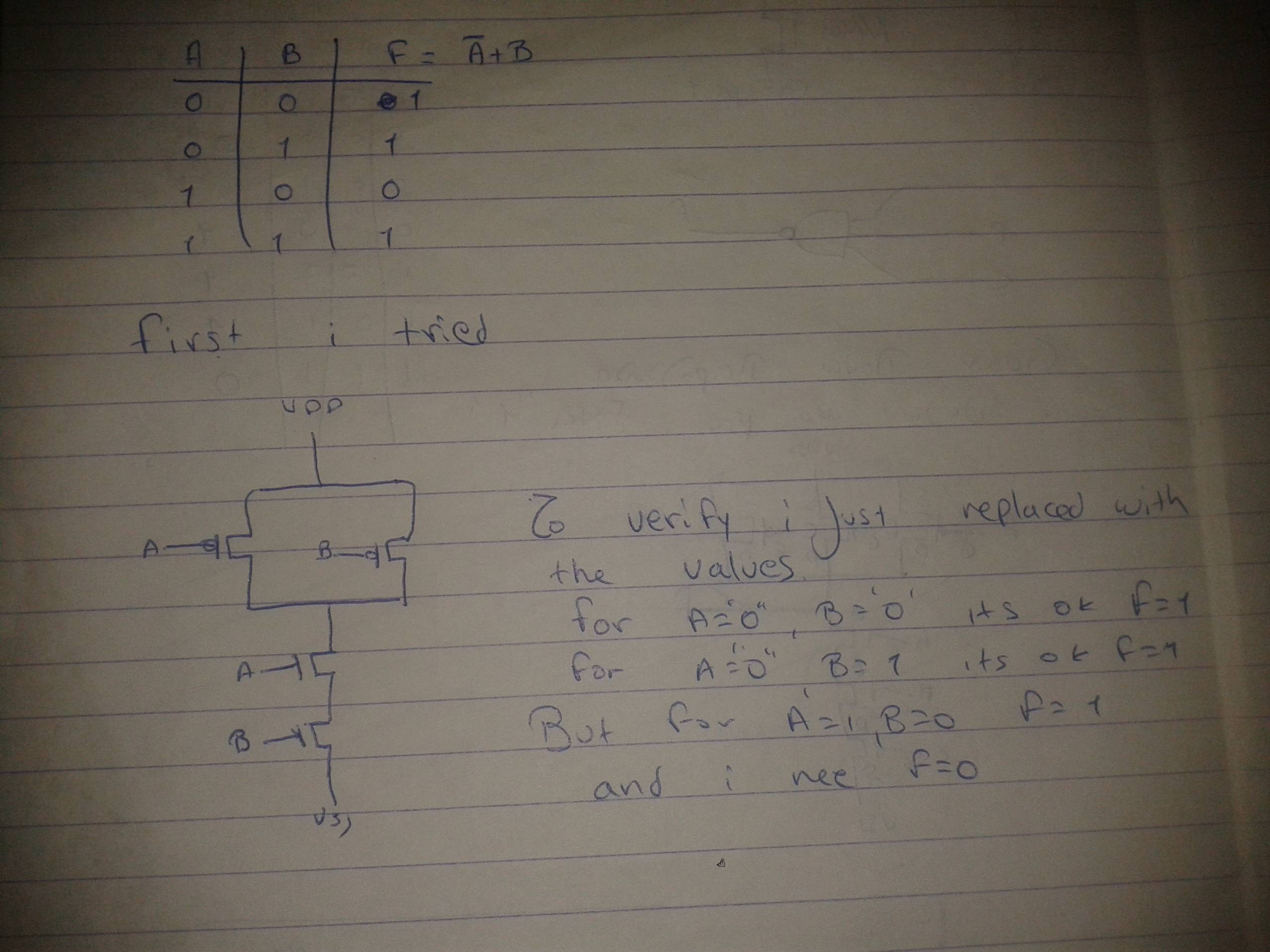
I have to create a CMOS circuit from the logic function: F= ~A + B (notA or B). I made the truth table but I'm stuck here trying to make the CMOS circuit. Any ideas anyone? Thanks!

CMOS.

I know it's the CMOS circuit for the NAND gate. I tried to change to get the results I want but I'm stuck.

\$\endgroup\$
3
  • \$\begingroup\$ i searched for this before i post the question. I m asking about this specific logic function. I m familiar with this but this one, i cant solve it. \$\endgroup\$ Commented Jan 22, 2015 at 0:12
  • \$\begingroup\$ Please show us what you've tried. In essence, everything you need is in the answer there. \$\endgroup\$
    – user17592
    Commented Jan 22, 2015 at 0:14
  • \$\begingroup\$ What was the circuit you drew? What did you do to verify? What is the expected result and what is the actual result? Please edit your question to provide more information. \$\endgroup\$
    – user17592
    Commented Jan 22, 2015 at 0:21

2 Answers 2

1
\$\begingroup\$

The base CMOS logic elements you have are NOT gates, NAND gates and NOR gates. So you need to convert your function to use only those gates. You have an OR gate in your function, so you need to convert this into one of the above three gates. There are two ways of doing this which stand out:

(1) What do you need to do to use a NOR gate? The answer to that is as simple as it seems. [Hint: how do you make a NOR gate into an OR gate]. Now you know the circuit in its base elements, simply join the CMOS equivalents together. [Hint: you will have 3 CMOS elements to connect up]

(2) The second option results in a much simpler CMOS implementation. It does however rely on a rather cool boolean logic equality: !A + !C = !(A . C). Using that equality, what must C equal to make the left hand side equal to your function? After you replace C, implement the function on the right hand side with CMOS elements. [Hint: you will have 2 CMOS elements to connect up]


FYI: The circuit in your picture is a NAND gate.

\$\endgroup\$
0
\$\begingroup\$

Accepted answer to the question How are logic gates created electronically? can clarify most of your doubts. So I recommend you tor read that answer before reading this.

The basic steps involved in CMOS implementation are explained below taking NAND gate as an example. Hope that you can implement your logic following these steps.

Step 1: Write the inverted logic.
ie, if you want to implement Y, then write the expression for \$\overline{Y}\$.

For NAND gate, $$Y=\overline{AB}$$ $$\overline{Y} = AB$$ So now Y should be low if both inputs are high.

Step 2: Implement the NMOS logic (the pulldown network).
From output line, draw NMOS transistors (with inputs connected at its gate) to ground to implement the logic \$\overline{Y}\$. For and logic, connect in series and for or logic connect in parallel.

For NAND gate, \$\overline{Y} = AB\$, so draw two NMOS in series as shown.
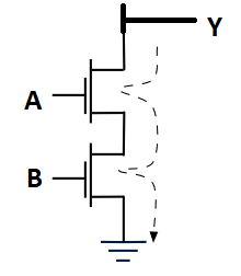
enter image description here

So now Y is low if both inputs are high.

Step 3: Draw the dual of NMOS circuit to implement PMOS circuit (the pull up network).
ie, Replace each series connection with parallel and parallel with series connection. Implement the resulting circuit using PMOS and connect it from output line to Vdd.

The dual of AB is A+B. So connect two PMOS transistors in parallel from Y to Vdd. enter image description here
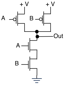
So now out will be high if one of the inputs are high. This completes the logic.
\$\endgroup\$

Not the answer you're looking for? Browse other questions tagged or ask your own question.