2
\$\begingroup\$

I am working on a design where I am encountering a strange issue with the use of series ferrite beads. In some of my designs, I have successfully used series ferrite beads on the positive power input without any problems. However, in my current project, I am facing an intermittent issue.

The design includes:

  1. Ferrite beads placed in series between on the positive power input.
  2. Parallel capacitors across the power supply input, typically after the ferrite beads.

My current design - (Max current consumption 4.5A-5A): Note: The system consumes 90W on it's peak performance, while input Voltage is 20V. sometimes the current my jump over 5A at power up (short time spikes), but the PSU can handle such peaks. enter image description here
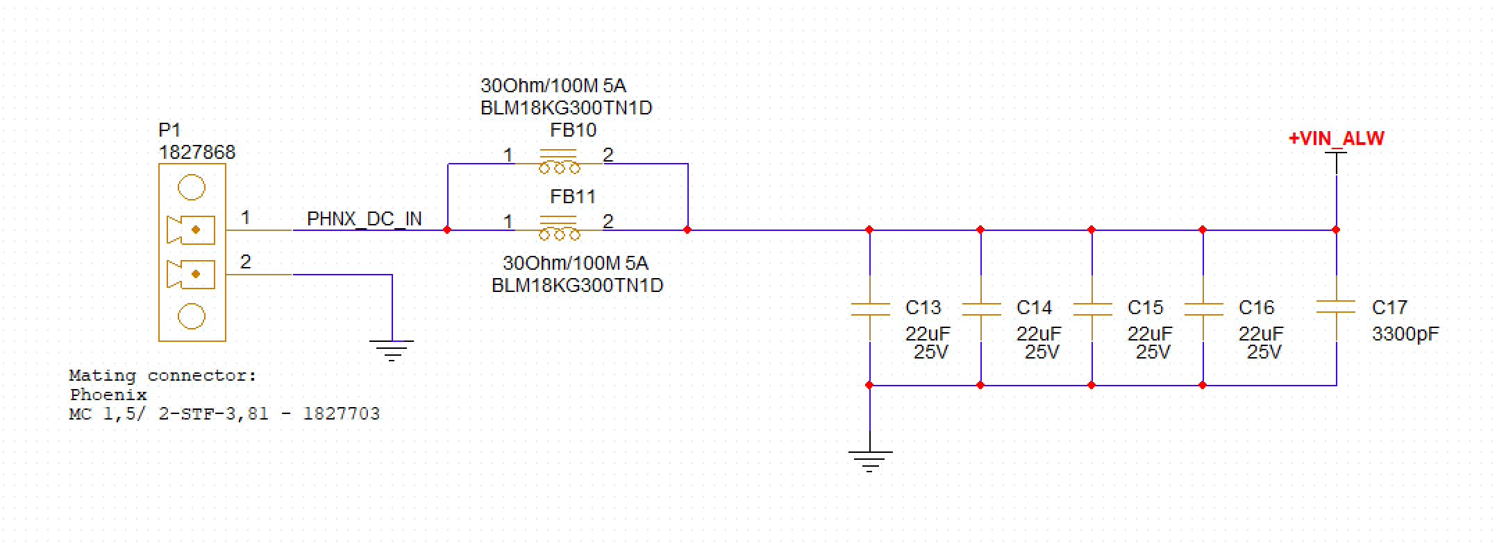
These are the type of capacitors I'm using: 22uF, 1uF, 3300pF

The issue occurs when frequently disconnecting and reconnecting the power supply. Occasionally, I experience a complete DC disconnection (Lab power supply shows 20V @ 0 W - which looks like there is high-impedance/open circuit), meaning no current flows through the system, although the voltage across the input capacitors is correct.

I suspect this might be related to the placement of the ferrite beads and their potential saturation, especially during inrush currents or transients caused by frequent power cycling.

However, in a previous design, this issue doesn't occur (max current consumption is 5A): enter image description here
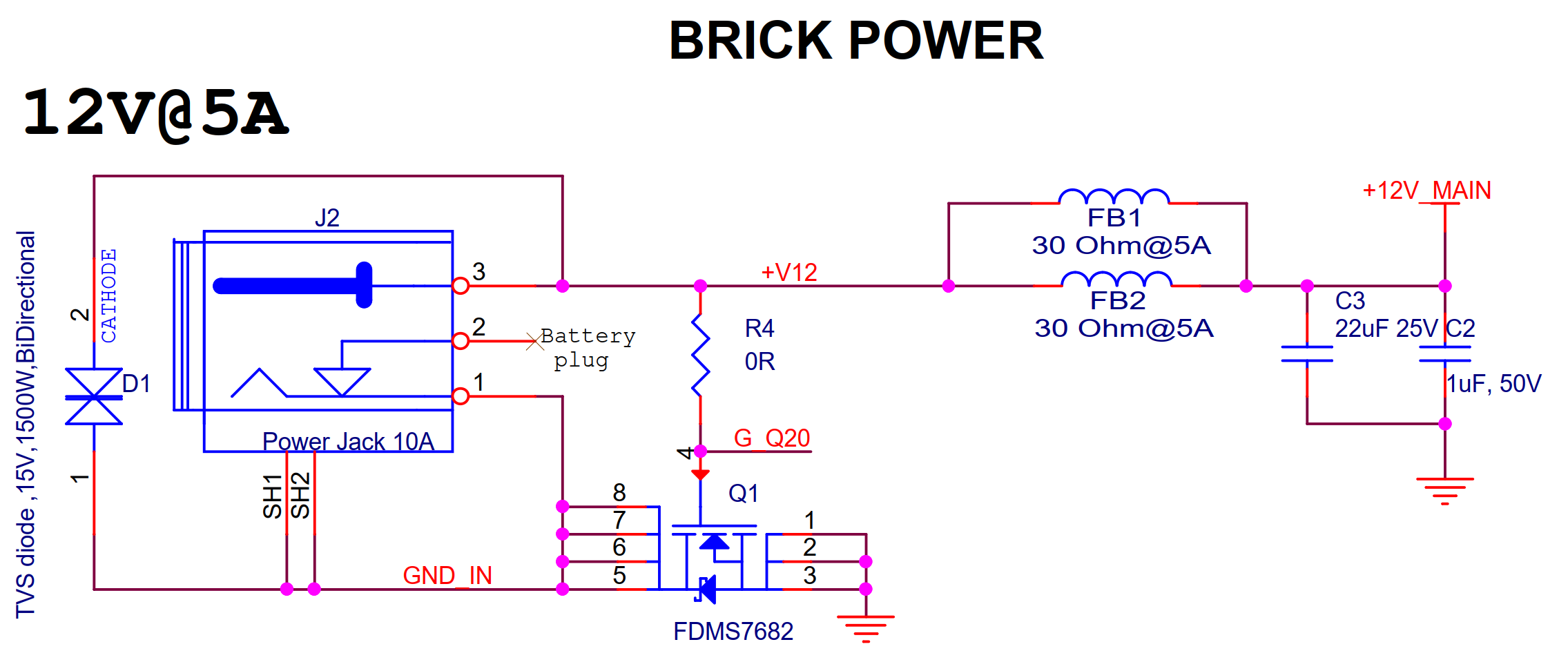
My Questions:

  1. What are the best practices for placing series ferrite beads on the positive input power line to achieve better EMC test results?
  2. How should the capacitors be placed relative to the ferrite beads to minimize the risk of saturation and ensure stable operation?
  3. Could the fact that there is no similar series ferrite beads at the GND input of the connector contribute to this issue?
  4. What other design considerations should I take into account to prevent DC disconnection during frequent power cycling?

After some research, I thought it might be a good idea to connecting the power supply negative pin to GNDC, and put series ferrite beads between GNDC and GND. this way, static discharge will see the path of least resistance to the Power Supply Ground, and Ferrite Beads make the resistance path to the GND higher.

Note: GNDC will be connected to the chassis of all connectors on the board.

Update from comments:

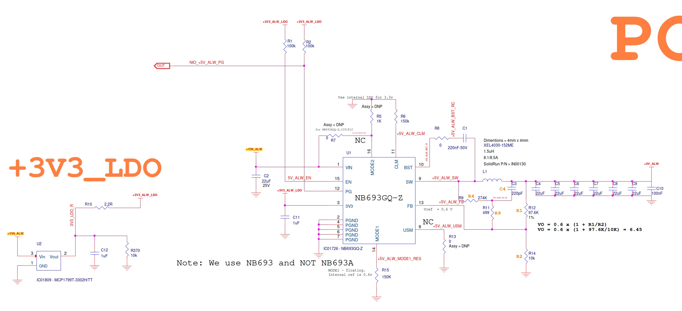
VIN_ALW goes on 5V DC-DC and an LDO on the Carrier board:

enter image description here

One thing I can tell for sure that when this issue happens, when I unplug the power connector (which is connected to LAB PSU), it takes around 12 seconds to discharge the capacitors.

UPDATE: I used the following setup to make the measurement with oscilloscope:

  1. N7020A Probe (Supports up to 2Ghz).
  2. N7022A Cable + N7021A Pigtail.
  3. EXR4104A Scope.

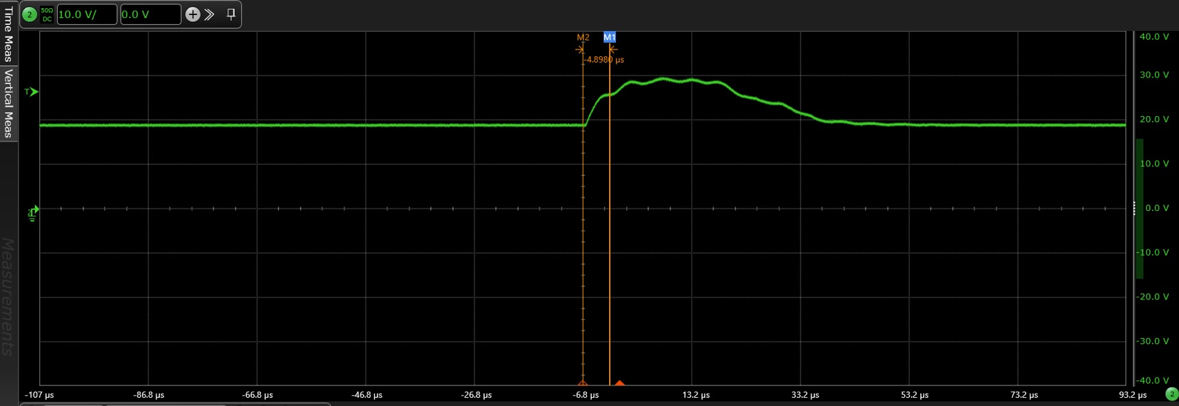
I was able to detect a peak voltage that reached 30V, which is above the NB693 maximum input range of 28V. This raises the suspicion that the issue might be related to the over-voltage protection mechanism of the DC-DC converter being triggered.

enter image description here

Follow up question based on previous measurements:

As mentioned before, reaching 30V peak after plugging and unplugging the power connector frequently, raises the suspicion that I might have got over-voltage protection lock in the DC-DC.

My question is, how would TVS diode would help as if it only re-directs the current to GND instead of making it go to the DC-DC circuit? it doesn't prevent VIN_ALW voltage (the vin to DC-DC) to reach the 30V peak. (assuming max allowed DC-DC vin voltage is 28V)

\$\endgroup\$
15
  • 3
    \$\begingroup\$ What is the character of your 'disconnection'? Physical removal of the power plug? Switched on-off-on? Also: The second (working) circuit has TVS diode. This play significant role in spikes reduction. \$\endgroup\$
    – smajli
    Commented May 16 at 10:46
  • \$\begingroup\$ @smajli Lab power supply shows 20V @ 0 W - which looks like there is high-impedance/open circuit. \$\endgroup\$ Commented May 16 at 10:56
  • \$\begingroup\$ BLM18KG300TN1D is rated 5A at 85deg Celcius, and 3.3A at 125deg Celcius. You said your load is at the level of 8 to 9Ams. Aren't ferrite beads overheating? \$\endgroup\$
    – smajli
    Commented May 16 at 11:16
  • \$\begingroup\$ Yes, but since there are two parallel ferrite beads, each one will deliver maximum 5A. so I assumed there will not be overheating/saturation. what am I missing? \$\endgroup\$ Commented May 16 at 12:00
  • 2
    \$\begingroup\$ Beware that ferrite beads typically saturate at quite low currents, a fraction of the RMS current rating (which is thermal only, not driven by characteristics). I was not able to find saturation current data on the BLM18KG300TN1. \$\endgroup\$ Commented May 16 at 12:34

3 Answers 3

5
\$\begingroup\$

Saturation is not a problem. The beads are just wire when saturated. They don't need to be functional to have the system powered on etc. They don't filter transients, in fact they contribute to them a little bit. The beads are there to absorb wideband RF currents and prevent them from turning into radiated emissions. As most things in engineering, they do it at a trade-off: you're trading high-frequency damping for parasitic inductance at low frequencies.

Combining low ESR capacitors with inductance of the wire in the ferrite beads (and the power supply cables feeding them) is the problem, though. A very common and insiduous problem. The regulator shuts down probably due to latch-up or input overvoltage trip.

There should be a fast power Schottky diode reverse connected from ground to the power bus on both sides of the ferrite beads. This protects from inductive kick-back below ground level.

There also needs to be a fast transient 24V-rated voltage suppressor in parallel with each of the previously mentioned Schottky diodes.

The switching buck should not have its maximum ratings exceeded when presented with 28V transients. Typically that means that you want a buck IC that can take 28V on the input, yet the design of the step-down regulator is of course optimized for operation on the usual 20V input.

Finally, you should be able to capture those transients on a digital oscilloscope. They will be potentially pretty sharp, so ensure you're using high-speed-signal probing techniques. And don't blow up the front-end.

\$\endgroup\$
3
  • 1
    \$\begingroup\$ Or a single unidirectional TVS can be used -- note that schottky have comparable voltage drop under surge conditions to PN diodes, so it doesn't really matter. If tighter clamping is required, I would suggest an active circuit, though this does get challenging to implement for short transients. (All the same, few things are that sensitive, to moderate reversal for short durations, so it doesn't come up often.) \$\endgroup\$ Commented May 17 at 2:48
  • 1
    \$\begingroup\$ Those ferrite beads with the input capacitance will form a resonant circuit that can create high voltage peaks with step-currents. I've been affected by this in the past. \$\endgroup\$
    – qrk
    Commented May 17 at 5:33
  • \$\begingroup\$ Interesting. that's really good stuff to remember. can you please see my question update regarding the TVS in this case? \$\endgroup\$ Commented May 27 at 15:26
7
\$\begingroup\$

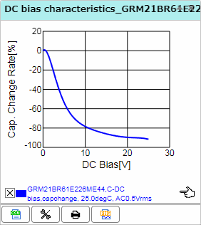
From the capacitor characteristics database,
https://ds.murata.co.jp/simsurfing/mlcc.html?partnumbers=%5B%22GRM21BR61E226ME44%22%5D&oripartnumbers=%5B%22GRM21BR61E226ME44K%22%5D&rgear=jomoqke&rgearinfo=com&md5=1715917607821

enter image description here

At a nominal input of 12V, these "22uF" caps are already a paltry 3.9uF each. In this regime, capacitance goes roughly inverse with voltage, so if the voltage doubles to 24V, capacitance falls to 2uF, etc.

If we input such a characteristic to an LC circuit, formed by the inductance of the power supply cable, and apply a transient equivalent to hot-plugging it, we find a peak voltage not just twice the applied voltage (which is the case for a constant-C capacitance), but many times higher still.

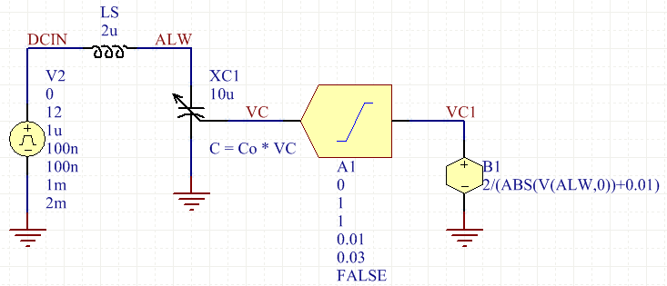
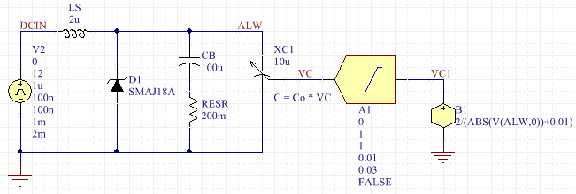
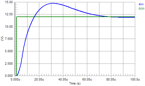
For example, here is a simulation demonstrating a dependent capacitor whose value is inverse with applied voltage, beyond some margin.

enter image description here

This uses a non-linear dependent (function) source, XSPICE LIMITER block, and a variable capacitor of my own design (links to my website) to approximate the situation in question.

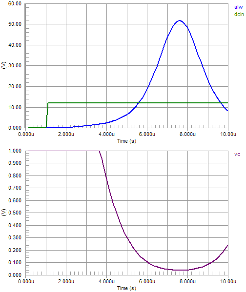
enter image description here

Notice the peak is 52V, far beyond the expected (linear case) 24V, and well beyond the nominal 12V input.

The linear case is already a surprise for those expecting to use, say, 18V-max devices on a 12V supply, but this behavior makes things so many times worse, still.

Some loss is required to constrain the peak. This can be done by clamping it directly, with a TVS, or providing a lossy "bulk" capacitor, typically electrolytic, whose ESR dominates and thus an overdamped response is obtained for most values of LS that might be connected.

As for LS, the inductance of wiring or cabling is on the order of 0.5uH per meter of length. This arises from the transmission line structure of a cable, and the low-frequency equivalent inductance of that transmission line.

(On a theoretical basis, we might envision the transient as myriad reflections back and forth on the transmission line, building up current flow as the line is highly mismatched at both ends -- there is a capacitor inside the power supply, and a capacitor at the inlet of your device, both having impedances very far from \$Z_0\$ of the cable. However, we aren't interested in the nanosecond-to-nanosecond history of this event, just the average behavior over some microseconds, so we invoke the lumped-equivalent approximation instead.)

With damping or clamping,

enter image description here

we see waveforms (damping dominant),

enter image description here

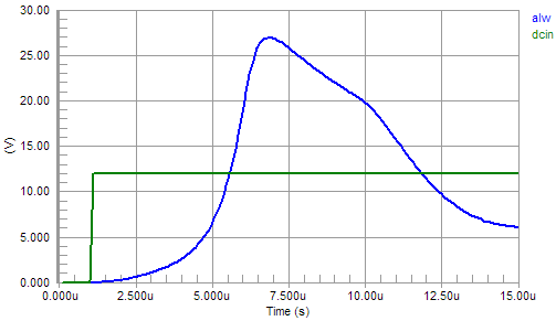
or clamping dominant (RESR = 1e6),

enter image description here

Damping is recommended in any case, to provide a positive and low impedance for the buck converter to operate into. Notice a buck converter has a negative incremental input resistance (current falls as voltage rises), so it can turn an LC resonant circuit into an oscillator.


This is not a complete answer, as without a datasheet, I cannot speak for the exact behavior your regulator is exhibiting, or what its ratings are, but this seems a likely prerequisite that must be solved before further evaluation can be performed.


This answer is another in a series of input filtering and inrush posts. For related reading, see:

An example with chaotic behavior:
DC/DC buck regulator regularly emits an audible clicking noise

Outright failure is most common:
Why did my DC/DC Buck Circuit fail?
DC-DC buck regulator MP2359 sometimes damaged when input voltage is high
Buck Converter dies unpredictably upon connecting power
5V LDO blowing up only when testing current draw
Why is my TPS62162DSGT regulator burning?
How to prevent buck regulator chip from blowing up when using near maximum input voltage?

\$\endgroup\$
1
  • \$\begingroup\$ Thanks Tim for the great info! seems like it's very hard to find High ESR caps such as Aluminum Electrolytic caps with a height lower than 2mm. (which is a mechanical limitation). Also, can you please check my follow up question regarding the TVS Diode? \$\endgroup\$ Commented May 27 at 15:29
4
\$\begingroup\$

Not absolutely sure but here is what I would try:

When you rapidly connect and disconnect power, you can put the device in one of its protection modes where the device latches into a low-power state. This state can only be cleared by cycling the enable line on the NB693.

First, get the part into this state and then short the enable line to ground. When it is released, the unit should start up.

You can then either attach the enable line to a processor or to an IC voltage supervisor chip of the type used to pull a reset line low if brownout occurs. You might even get away with a diode/capacitor/resistor arrangement used on reset lines on small controllers. However, you'll have to experiment with rapid plugging and unplugging to try to find a set of values that will definitely pull the enable line low and hold it down every time you disconnect.

\$\endgroup\$

Your Answer

By clicking “Post Your Answer”, you agree to our terms of service and acknowledge you have read our privacy policy.

Not the answer you're looking for? Browse other questions tagged or ask your own question.