I am working on a design where I am encountering a strange issue with the use of series ferrite beads. In some of my designs, I have successfully used series ferrite beads on the positive power input without any problems. However, in my current project, I am facing an intermittent issue.
The design includes:
- Ferrite beads placed in series between on the positive power input.
- Parallel capacitors across the power supply input, typically after the ferrite beads.
My current design - (Max current consumption 4.5A-5A):
Note: The system consumes 90W on it's peak performance, while input Voltage is 20V. sometimes the current my jump over 5A at power up (short time spikes), but the PSU can handle such peaks.
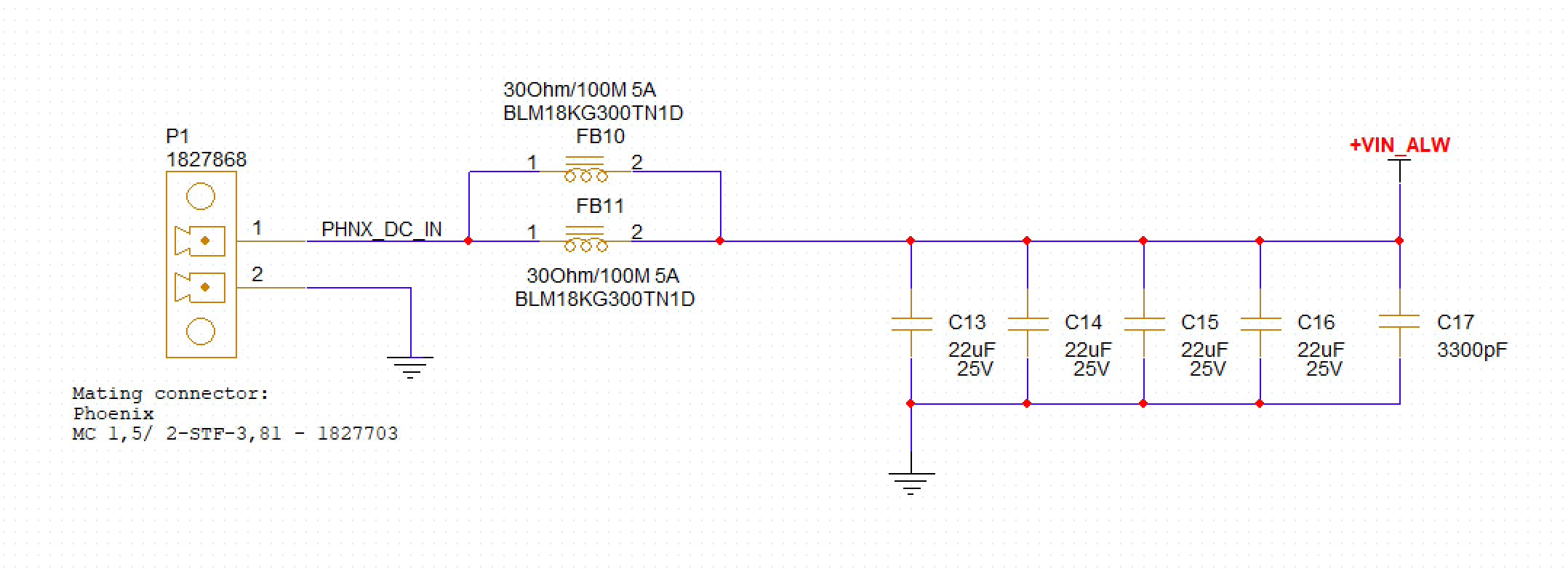
These are the type of capacitors I'm using: 22uF, 1uF, 3300pF
The issue occurs when frequently disconnecting and reconnecting the power supply. Occasionally, I experience a complete DC disconnection (Lab power supply shows 20V @ 0 W - which looks like there is high-impedance/open circuit), meaning no current flows through the system, although the voltage across the input capacitors is correct.
I suspect this might be related to the placement of the ferrite beads and their potential saturation, especially during inrush currents or transients caused by frequent power cycling.
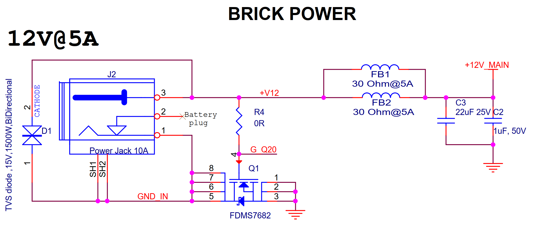
However, in a previous design, this issue doesn't occur (max current consumption is 5A):
My Questions:
- What are the best practices for placing series ferrite beads on the positive input power line to achieve better EMC test results?
- How should the capacitors be placed relative to the ferrite beads to minimize the risk of saturation and ensure stable operation?
- Could the fact that there is no similar series ferrite beads at the GND input of the connector contribute to this issue?
- What other design considerations should I take into account to prevent DC disconnection during frequent power cycling?
After some research, I thought it might be a good idea to connecting the power supply negative pin to GNDC, and put series ferrite beads between GNDC and GND. this way, static discharge will see the path of least resistance to the Power Supply Ground, and Ferrite Beads make the resistance path to the GND higher.
Note: GNDC will be connected to the chassis of all connectors on the board.
Update from comments:
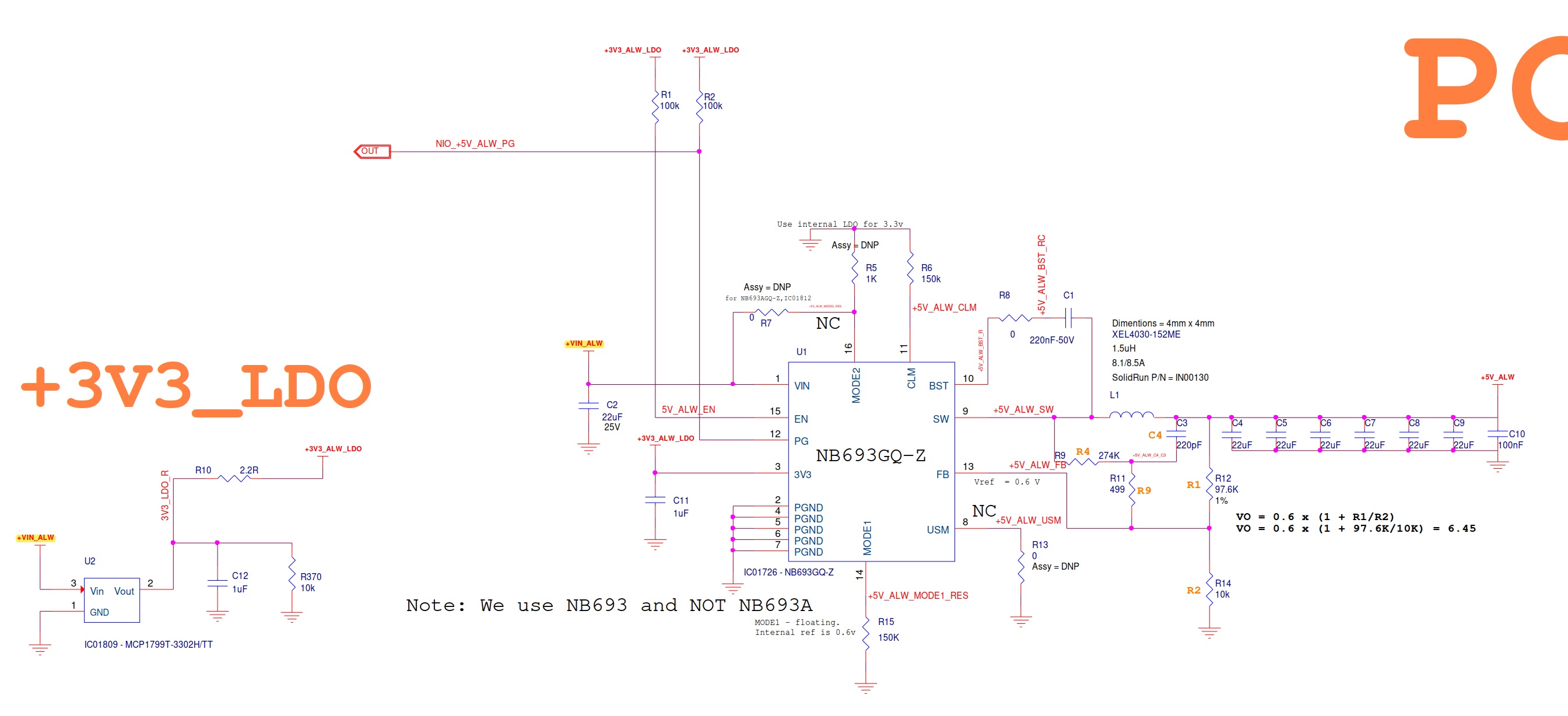
VIN_ALW goes on 5V DC-DC and an LDO on the Carrier board:
One thing I can tell for sure that when this issue happens, when I unplug the power connector (which is connected to LAB PSU), it takes around 12 seconds to discharge the capacitors.
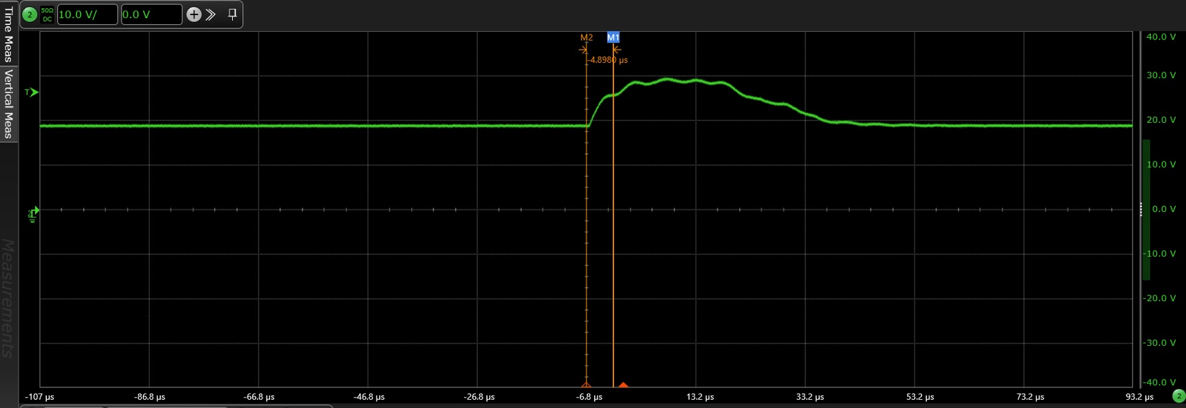
UPDATE: I used the following setup to make the measurement with oscilloscope:
- N7020A Probe (Supports up to 2Ghz).
- N7022A Cable + N7021A Pigtail.
- EXR4104A Scope.
I was able to detect a peak voltage that reached 30V, which is above the NB693 maximum input range of 28V. This raises the suspicion that the issue might be related to the over-voltage protection mechanism of the DC-DC converter being triggered.
Follow up question based on previous measurements:
As mentioned before, reaching 30V peak after plugging and unplugging the power connector frequently, raises the suspicion that I might have got over-voltage protection lock in the DC-DC.
My question is, how would TVS diode would help as if it only re-directs the current to GND instead of making it go to the DC-DC circuit? it doesn't prevent VIN_ALW voltage (the vin to DC-DC) to reach the 30V peak. (assuming max allowed DC-DC vin voltage is 28V)

