25
\$\begingroup\$

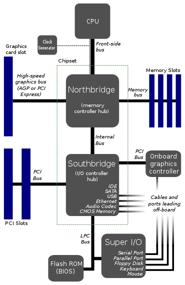
I found a motherboard architecture here:

enter image description here

This looks to be the typical layout of motherboards. EDIT: Well, apparently it's not so typical anymore.

Why does the CPU connect to only 1 bus? That front-side bus looks like a major bottleneck. Wouldn't it be better to give 2 or 3 buses straight into the CPU?

I imagine one bus for the RAM, one for graphics card, and one for some kind of bridge to the harddrive, usb ports, and everything else. The reason I split it up this way is because harddrive data rates are slow compared to memory.

Is there something very hard about doing it this way? I don't see how cost could come into it, because the existing diagrams already have no less than seven buses. In fact, by using more direct buses, we could reduce the total number of buses and maybe even one of the bridges.

So anything wrong with this? Is there a major disadvantage somewhere? The only thing I can think of is perhaps more complexity in the CPU and kernel, which makes me think this bottleneck bus architecture is how it was done in the old days when things were less sophisticated, and the design stays the same for standardization.

EDIT: I forgot to mention the Watchdog Monitor. I know I've seen it in some diagrams. Presumably a bottleneck bus would make it easier for the watchdog to monitor everything. Could that have something to do with it?

\$\endgroup\$
3
  • 9
    \$\begingroup\$ That's a very old approach. Nowadays the CPU has the root complex and memory controller built in - so connects directly to PCIe devices, RAM, and what is effectively the south bridge. For example this \$\endgroup\$ Commented Feb 26, 2016 at 2:32
  • \$\begingroup\$ @TomCarpenter Yeah that's starting to look more like it. The diagram I posted is what I've seen "everywhere", including school, so I figured it was more typical. \$\endgroup\$
    – DrZ214
    Commented Feb 26, 2016 at 2:36
  • 7
    \$\begingroup\$ That diagram above is still relevant. These days that is not a diagram of a motherboard but the CPU itself. Replace "CPU" with "core" and "chipset" with "CPU". \$\endgroup\$
    – slebetman
    Commented Feb 26, 2016 at 7:39

4 Answers 4

43
\$\begingroup\$

The approach which you show is quite an old topology for motherboards - it predates PCIe which really puts it back somewhere in the '00s. The reason is primarily due to difficulties of integration.

Basically 15 years ago the technology to integrate everything onto a single die was virtually non-existent from a commercial standpoint, and doing so was incredibly difficult. To integrate everything would result in very large silicon die sizes which in turn leads to much lower yield. The yield is essentially how many dies you lose on a wafer due to defects - the bigger the die the higher the probability of a defect.

To combat this, you simply split the design up into multiple chips - in the case of motherboards, this ended up being CPU, North Bridge, and South Bridge. The CPU is limited to just the processor with a high speed interconnect (referred to as the front-side bus as far as I recall). You then have the North Bridge which integrates the memory controller, graphics connection (e.g. AGP, an ancient technology in computing terms), and another slower link to the South Bridge. The South Bridge was used to handle expansion cards, hard drives, CD drives, audio, etc.


In the last 20 years the ability to manufacture semiconductors at smaller and smaller process nodes with higher and higher reliability means integrating everything onto a single chip becomes possible. Smaller transistors means higher density so you can fit more in, and improved processes in manufacture mean higher yield. In fact not only is it more cost effective, but also it has become vital to maintain the increases of speed in modern computers.

As you correctly point out, having one interconnect to a north bridge becomes a bottleneck. If you can integrate everything onto the CPU, including the PCIe Root Complex and system memory controller, you suddenly have an extremely high speed link between key devices for graphics and computing - on the PCB you are maybe talking speeds of the order of Gbps, on the die you can achieve speeds on the order of Tbps!

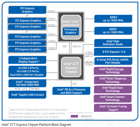
This new topology is reflected in this diagram:

New Topology

Image Source

In this case as you can see, the graphics and memory controllers are both integrated onto the CPU die. While you still have one link out to what is effectively a single chipset made of some bits of the north bridge and the south bridge (the chipset in the diagram), this nowadays in incredibly fast interconnect - maybe 100+Gbps. Still slower than on the die, but much faster than the old front-side buses.

Why not just integrate absolutely everything? Well motherboard manufacturers still want some customisability - how many PCIe slots, how many SATA connections, what audio controller, etc.

In fact some mobile processors do integrate even more onto the CPU die - think single board computers using ARM processor variants. In this case, because ARM lease out the CPU design, manufacturers can still customise their dies as they see fit and integrate whatever controllers/interfaces they desire.

\$\endgroup\$
8
  • \$\begingroup\$ +1, you beat me to it :) Nice answer, especially for the historical reasons for architecture design. \$\endgroup\$
    – uint128_t
    Commented Feb 26, 2016 at 3:03
  • \$\begingroup\$ Thank you, especially the second paragraph hit home. However, on the die you can achieve speeds on the order of Tbps! Yikes, isn't that beginning to outrun the CPU's ability to process it fast enough? \$\endgroup\$
    – DrZ214
    Commented Feb 26, 2016 at 3:19
  • 3
    \$\begingroup\$ @DrZ214 They are not PCI, they're PCIe which is a serial bus rather than a parallel one. PCIe is either 2.5Gbps, 5Gpbs or 8Gbps per lane in both directions (full duplex) - with 16 lane being the widest usually seen giving a theoretical maximum 128Gbps in both directions. And yes, the comment above about the speeds of the processor was intentionally overly simplistic, but not unrealistic - unrelated to CPUs, I am working on an FPGA design at the moment which processes data at 315Gbps, and that is nowhere near the full performance possible of the FPGA, what's limiting that is lack of data! \$\endgroup\$ Commented Feb 26, 2016 at 5:17
  • 1
    \$\begingroup\$ What's interesting is that this represents a shift back towards the architecture of even older systems, where the memory and storage buses (etc.) went directly to the CPU. \$\endgroup\$
    – Chris H
    Commented Feb 26, 2016 at 8:59
  • 1
    \$\begingroup\$ @DrZ214 a "lane" is a single bit wide, a clock/data signal sent as two pairs. The unique thing about PCIe compared to, say, the DDR bus is that PCIe can freely aggregate and deaggregate lanes, whereas most buses you have to take all or nothing. \$\endgroup\$
    – pjc50
    Commented Feb 26, 2016 at 10:04
9
\$\begingroup\$

I can't say I'm an expert in a computer architecture, but I'll take a shot at answering your questions.

This looks to be the typical layout of motherboards.

As Tom mentioned, this is no longer true. Most modern CPUs have an integrated northbridge. The southbridge is typically either integrated or made unnecessary by new architecture; Intel's chipsets "replace" the southbridge with the Platform Controller Hub, which communicates directly with the CPU via a DMI bus.

Why does the CPU connect to only 1 bus? That front-side bus looks like a major bottleneck. Wouldn't it be better to give 2 or 3 buses straight into the CPU?

Wide (64-bit) busses are expensive, they require a large number of bus transceivers and many I/O pins. The only devices that require a huge screaming fast bus are the graphics card and RAM. Everything else (SATA, PCI, USB, serial and so on) is comparatively slow, and not being constantly accessed. Hence why in the above architecture, all those "slower" peripherals are lumped together through the southbridge as a single bus device: the processor does not want to have to arbitrate every little bus transaction, so all the slow/infrequent bus transactions can be aggregated and managed by the southbridge, which then connects to the other peripherals at a much more leisurely speed.

Now, it's important to mention that when I say above that SATA/PCI/USB/serial are "slow", that's mainly a historical point, and is becoming less true today. With the adoption of SSDs over spinny disks and fast PCIe peripherals, as well as USB 3.0, Thunderbolt, and maybe 10G ethernet (soon), "slow" peripheral bandwidth is quickly becoming very significant. In the past, the bus between the northbridge and southbridge wasn't much of a bottle neck, but now that is no longer true. So yes, architectures are moving toward more buses attached directly to the CPU.

Is there something very hard about doing it this way? I don't see how cost could come into it, because the existing diagrams already have no less than seven buses.

It would be more buses for the processor to manage, and more processor silicon to deal with busses. Which is expensive. In the above diagram, not all buses are equal. The FSB is screaming fast, the LPC is not. Fast buses require fast silicon, slow buses don't, so if you can move slow buses from the CPU to another chip, it makes your life easier.

However, as mentioned above, with the increasing popularity of high bandwidth devices, more and more buses connect directly to the processor, particularly in SoC/more highly integrated architectures. By putting more and more controllers on the CPU die, very high bandwidth is easier to attain.

EDIT: I forgot to mention the Watchdog Monitor. I know I've seen it in some diagrams. Presumably a bottleneck bus would make it easier for the watchdog to monitor everything. Could that have something to do with it?

No, that's not really what a watchdog does. A watchdog is simply to restart various things when/if they lock up; it doesn't really look at everything moving across the bus (it's far less sophisticated than that!).

\$\endgroup\$
3
  • 2
    \$\begingroup\$ Fast buses require fast silicon, slow buses don't What exactly does fast silicon mean? Higher-purity silicon? Or are you saying slow buses can use a different element than silicon? Either way, I thought silicon was a pretty cheap material. Interesting bit about the watchdog too. I might ask a related question about it. \$\endgroup\$
    – DrZ214
    Commented Feb 26, 2016 at 3:25
  • 1
    \$\begingroup\$ A fast bus would typically be part of a high-performance device e.g. a CPU. The bus interface requires space and connections to other parts of the chip. Silicon area on a processor die is much more expensive than a much slower chip, because the process size is smaller and fabrication/packaging is more difficult. Therefore, it's cheaper to restrict the devices on the FSB to only those devices that actually require such bandwidth. However, as more controllers are integrated with the CPU on the same die (a SoC), this is no longer as true. \$\endgroup\$
    – uint128_t
    Commented Feb 26, 2016 at 3:30
  • \$\begingroup\$ Even though slow buses do not require fast silicon, it is not uncommon to find very fast drivers on slow interfaces, which can create a major headache for PCB layout. I have seen ordinary PCI (max speed 133MHz on PCI-X) with rise and fall times of less than 300 ps, as the vendors are using a standard I/O cell. I know PCI, as an interface, is not normally available on new processors, but this issue is applicable elsewhere. \$\endgroup\$ Commented Feb 26, 2016 at 8:10
6
\$\begingroup\$

The number of buses to which a CPU will directly connect will generally be limited to the number of distinct parts of the CPU that could access things simultaneously. It's not uncommon, especially in the world of embedded processors and DSPs, for a CPU to have a bus for programs and a bus for data, and allow both to operate simultaneously. A typical uniprocessor, however, will only benefit from fetching one instruction per instruction cycle, and will only be able to access one data memory location per instruction cycle, so there won't be much benefit to going beyond one program-memory bus and one data-memory bus. To enable certain kinds of math to be performed upon data fetched from two different streams, DSPs will often have special instructions which will use the program-memory bus to receive some of their data so they can fetch two numbers per cycle (or else load one and store one).

With processors that have multiple execution units, it may be helpful to have a separate bus for each, so that if there are multiple "outside" buses units which need to fetch things from different "outside" buses can do so without interference. Unless there is a logical reason why the things which are accessed by different execution units will be accessible through different buses outside the CPU, however, having separate buses from the CPU feed into an arbitration unit which can only relay one request at a time to a particular external device won't help anything. Buses are expensive, so having two execution units sit on one bus is generally cheaper than using separate buses. If using separate buses will allow a major performance improvement, that may justify the cost, but otherwise any resources (chip area, etc.) that would be consumed with a separate bus could be better utilized for other purposes.

\$\endgroup\$
0
\$\begingroup\$

Consider the number of pins required on the CPU packages to have multiple wide buses. For example, eight CPU cores each with a 64-bit data bus, plus assorted other pins for other purposes. Are there any CPU packages available today with perhaps 800 pins?

\$\endgroup\$
2
  • \$\begingroup\$ Why wouldn't there be? A 32x32 ball grid array and multi layered PCB doesn't sound like a difficult problem (on a relative scale). The hardware engineers are amazing. // Think about how wide and clumsy RAM cards can be, and still clock in at 1.6 GHz (625 picoseconds). If the electric signals travel at 2/3 c, the longest trace can only be 6 cm long, and just a few mm difference in length will cause noticeable timing offsets. // And I'd guess that the crosstalk between layers wouldn't be much worse than between traces on the same layer. \$\endgroup\$
    – Oskar Skog
    Commented Apr 5, 2017 at 18:18
  • \$\begingroup\$ "Are there any CPU packages available today with perhaps 800 pins?" Oh yes. Packages with 1100+ pins were already commonplace when this answer was written. And nowadays, there's LGA3647 for some Skylake-EX server CPUs… \$\endgroup\$
    – user39382
    Commented Feb 6, 2018 at 6:20

Your Answer

By clicking “Post Your Answer”, you agree to our terms of service and acknowledge you have read our privacy policy.

Not the answer you're looking for? Browse other questions tagged or ask your own question.